Workholding Safety: Machine Tool Automation and Retrofitting Engineers
Essential safety standards and compliance guidelines for machine tool automation and retrofitting engineers upgrading vises, chucks, and fixtures.
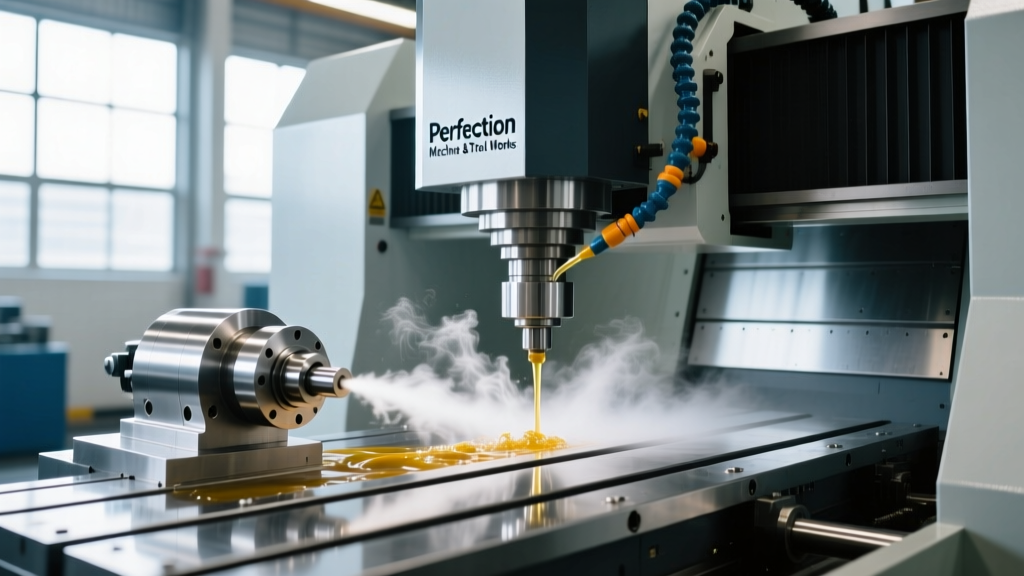
When machine tool automation and retrofitting engineers convert legacy manual lathes and mills into robotic-tended cells, workholding becomes the primary liability vector. A manual operator inherently monitors clamping integrity; an automated cell relies entirely on engineered safety controls. If a retrofitted hydraulic chuck loses pressure mid-cycle, the resulting kinetic energy of an ejected workpiece can easily penetrate standard polycarbonate enclosures, leading to catastrophic failure and severe OSHA violations.
This guide details the exact compliance frameworks, hardware specifications, and validation protocols required to safely automate vises, chucks, and custom fixtures in 2026.
The Compliance Gap in Legacy Retrofitting
The most common compliance failure in machine tool retrofitting is treating automated workholding as a simple pneumatic/hydraulic swap without integrating safety-rated feedback loops. Under OSHA 1910.212 (General Requirements for All Machines), any point of operation that exposes a worker to injury must be guarded. In lights-out or automated tending, the 'guard' is the interlocked workholding system itself.
⚠️ Compliance Warning: Simply adding a standard solenoid valve to a manual chuck does not meet ANSI B11.0 or ISO 13849-1 standards. If the facility loses compressed air or hydraulic pressure, standard single-acting valves will vent, causing the chuck to open. Automated cells require dual-circuit, monitored safety valves with pressure-maintenance accumulators.According to the Association for Manufacturing Technology (AMT), adherence to the ANSI B11 series is the benchmark for machine tool safety in North America. Retrofitting engineers must design workholding systems that default to a 'clamped' or 'safe' state upon e-stop activation or power loss.
Workholding Actuation and Safety Matrix
Selecting the correct actuation method dictates the required safety interlocks. The matrix below outlines the compliance requirements for different workholding types in automated environments.
| Workholding Type | Actuation Method | Clamp Force Variance | Required Safety Interlocks (ISO 13849-1) |
|---|---|---|---|
| Standard CNC Vise | Manual / Torque Wrench | High (Operator dependent) | Not permitted in unguarded automated cells |
| Air-Over-Hydraulic Vise | Pneumatic Booster | Low (Regulated to ±2%) | Category 1 / PLc (Pressure switch monitoring) |
| Power Chuck (Lathe) | Hydraulic Rotary Union | None (Constant pressure) | Category 3 / PLd (Dual pressure monitoring + RPM interlock) |
| Electro-Mechanical Chuck | Servo Motor / Drive | None (Torque controlled) | Category 4 / PLe (Safe Torque Off + position feedback) |
Engineering Controls for Hydraulic Power Chucks
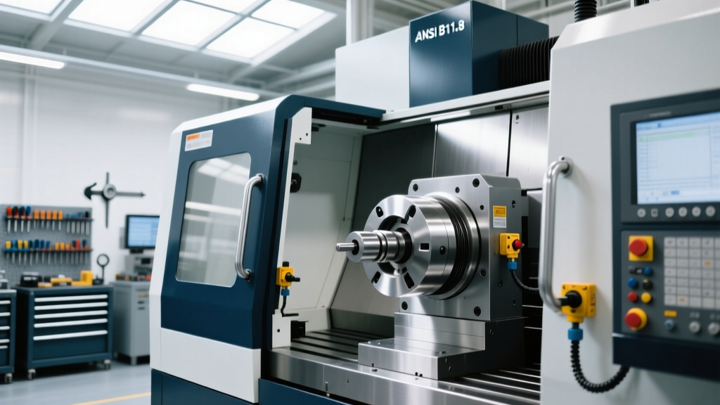
When retrofitting a manual lathe (e.g., a 15-inch engine lathe) with a power chuck like the Kitagawa B-210 or SMW Autoblok KNCS-N, the hydraulic power unit (HPU) must be engineered for fail-safe operation. A standard 10-inch chuck requires approximately 40 bar (580 psi) of hydraulic pressure to maintain 120 kN of clamping force at 2,500 RPM against centrifugal jaw lifting.
The Dual-Circuit Safety Valve Requirement
Standard 4/3 directional control valves are non-compliant for automated lathe chucks. Retrofitting engineers must install cross-ported, dual-coil safety valves (such as those manufactured by Herion or Bosch Rexroth). These valves feature internal monitoring switches that detect spool position. If one coil fails to shift, the monitoring switch prevents the machine cycle from starting and triggers a Category 3 Safe Stop 1 (SS1) on the CNC drive.
'Centrifugal force reduces the effective clamping force of power chuck jaws by up to 60% at maximum RPM. Automated systems must calculate and monitor the exact pressure-to-RPM ratio dynamically via the CNC PLC to prevent workpiece ejection.'
To mitigate pressure drops during power failures, a nitrogen-charged hydraulic accumulator (typically 1 to 2.5 liters, pre-charged to 60% of system pressure) must be installed downstream of the safety valve. This accumulator maintains clamping force long enough for the spindle to execute a controlled ramp-down to zero RPM.
Retrofitting Mechanical Vises for Robotic Tending
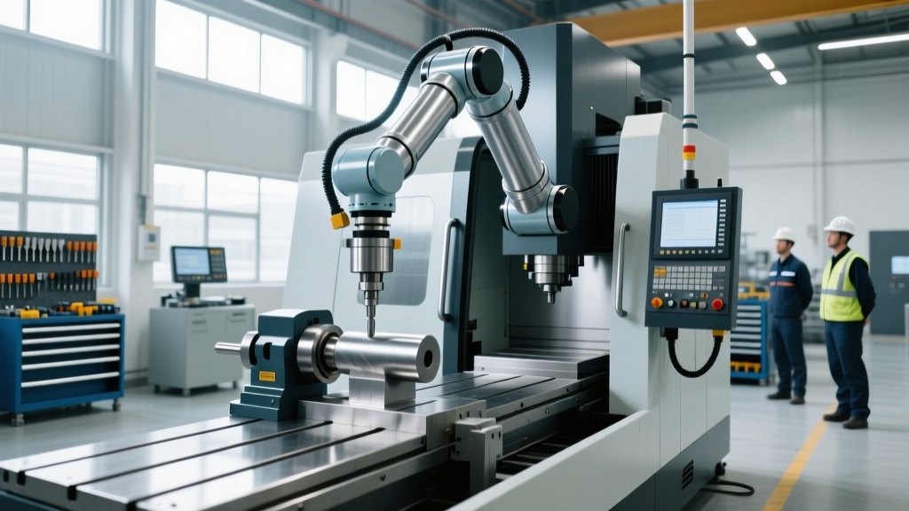
For vertical machining centers (VMCs) utilizing robotic arms for part loading, standard mechanical vises like the Kurt DX6 must be retrofitted with automated clamping and verification systems. The most reliable and cost-effective method is utilizing an air-over-hydraulic intensifier pump (e.g., Enerpac P-Series) paired with inductive proximity sensors.
Sensor Integration and PLC Logic
Simply monitoring air pressure is insufficient for compliance. The workpiece must be verified as seated and clamped. Engineers should integrate Balluff BES M12MI or IFM IGS204 inductive sensors directly into the movable jaw of the vise.
- Part Seated Verification: A sensor in the fixed jaw detects the part bottoming out against the parallel or step block.
- Clamp Force Verification: A pressure transducer (e.g., IFM PK6522) on the hydraulic line confirms the intensifier has reached the target 4,500 psi.
- Jaw Position Verification: A sensor on the movable jaw confirms the vise has closed within a 0.020-inch tolerance window, ensuring the part is not skewed or clamped on a chip.
These three signals must be wired into the machine's safety PLC (such as a Pilz PNOZ or FANUC Dual Check Safety module) using an AND logic gate. The robot is only permitted to retract, and the spindle is only permitted to engage, when all three conditions are met and locked via a safe output relay.
💡 Retrofitting Cost Insight: Upgrading a standard VMC cell with two Kurt DX6 vises, an Enerpac air-over-hydraulic pump, dual pressure transducers, and six Balluff proximity sensors typically costs between $3,800 and $4,500 in hardware. This is a fraction of the $15,625 maximum OSHA penalty for a single serious machine guarding violation in 2026.Custom Fixture Validation and Pull-Testing
When designing custom tombstones or dedicated fixtures for automated horizontal machining centers (HMCs), static clamping force calculations are not enough. Vibration, interrupted cuts, and coolant pressure can induce micro-movements that lead to catastrophic part failure.
Retrofitting engineers must perform dynamic pull-testing using a piezoelectric dynamometer (such as the Kistler 9257B) mounted to the fixture. The validation protocol requires:
- Applying a static pull force equal to 150% of the maximum calculated cutting force vector.
- Running a 15-minute interrupted cut simulation at full spindle RPM and coolant pressure (typically 300 psi through-spindle).
- Measuring part displacement using a 0.0001-inch resolution dial indicator or laser displacement sensor.
- Documenting the torque values of all fixture strap bolts using a calibrated digital torque wrench, recorded in the cell's safety validation dossier.
For automated cells handling heavy castings (over 100 lbs), compliance with OSHA guidelines for robotics and automated systems mandates that the fixture design includes physical hard-stops and fail-safe mechanical locks (such as spring-loaded detent pins) that engage if hydraulic pressure is lost, preventing the heavy part from shifting under gravity.
Summary of Compliance Deliverables
Before signing off on an automated workholding retrofit, the engineering team must deliver a comprehensive safety dossier. This must include the hydraulic/pneumatic schematic highlighting safety-rated components, the ISO 13849-1 SISTEMA calculation report proving the required Performance Level (PL), and the physical test logs verifying clamp force retention under simulated power-loss conditions. Treating workholding as a critical safety system, rather than a mere tooling accessory, is the defining hallmark of compliant machine tool automation.