Machine Tool Lubrication at Perfection Machine & Tool Works
Explore CNC machine tool lubrication systems, way oil schedules, and spindle cooling techniques used by Perfection Machine & Tool Works for precision.
Anatomy of High-Precision CNC Lubrication Systems
Achieving sub-micron tolerances on multi-axis CNC machining centers requires more than rigid castings and high-resolution encoders; it demands absolute mastery over friction and thermal growth. At facilities operating at the caliber of Perfection Machine & Tool Works, machine tool lubrication is treated as a critical fluid power system rather than a passive maintenance checklist. The interaction between way surfaces, spindle bearings, and ball screws dictates the ultimate geometric accuracy of the machined part.
Modern machining environments utilize centralized, automated lubrication networks that deliver precise fluid volumes at calculated intervals. This technical breakdown explores the exact specifications, fluid chemistries, and operational schedules required to maintain thermal stability and eliminate stick-slip phenomena in high-performance machine tools.
Way Lubrication: Overcoming Stick-Slip and Shear Degradation
The linear axes of a CNC mill or lathe rely on way lubricants to prevent 'stick-slip'—a phenomenon where static friction exceeds kinetic friction, causing jerky motion at low feed rates (typically below 0.5 inches per minute). To combat this, Perfection Machine & Tool Works specifies ISO VG 68 way oils formulated with specific friction modifiers and tackifiers.
Tackifier Chemistry and High-Pressure Coolant Washout
Standard hydraulic oils lack the adhesive properties required to cling to vertical way surfaces. Way oils utilize polyisobutylene or polymethacrylate tackifiers to increase adhesiveness. However, in modern shops using high-pressure through-spindle coolant (TSC) systems operating at 1,000 PSI, these tackifiers are subjected to extreme mechanical shear and washout.
- Demulsibility Requirement: Way oil must rapidly separate from water-soluble coolants. Fluids must pass the ASTM D1401 demulsibility test, separating 40ml of oil from 40ml of water in under 30 minutes to prevent the formation of emulsified 'tramp oil' that clogs coolant filters and promotes anaerobic bacteria growth.
- Copper Corrosion Inhibitors: Because way systems often route near bronze worm gears and copper-nickel thrust washers, the fluid must pass ASTM D130 copper strip corrosion tests (rating 1B or better).
Spindle Thermal Management: Oil-Air vs. Oil-Jet Systems
The spindle is the primary heat generator in a CNC machine. Thermal expansion of the spindle shaft directly translates to Z-axis tool tip displacement. To maintain thermal equilibrium within a ±0.1°C tolerance, high-speed spindles (15,000+ RPM) rely on advanced SKF lubrication solutions utilizing either oil-air mist or oil-jet delivery.
Comparative Analysis: Spindle Lubrication Architectures
| Parameter | Oil-Air Mist Lubrication | Oil-Jet (Under-Race) Lubrication |
|---|---|---|
| Typical Speed Limit | Up to 2,000,000 DN factor | Up to 1,500,000 DN factor |
| Fluid Viscosity | ISO VG 10 (e.g., 10 cSt @ 40°C) | ISO VG 22 to VG 32 |
| Cooling Mechanism | Evaporative cooling + minimal convection | Direct convective heat transfer via high-volume flow |
| Operating Pressure | 35 to 70 PSI (Air), 2 to 5 PSI (Oil) | 150 to 300 PSI (Pump pressure) |
| Chiller Requirement | Not strictly required for oil | Mandatory oil chiller (±0.1°C control) |
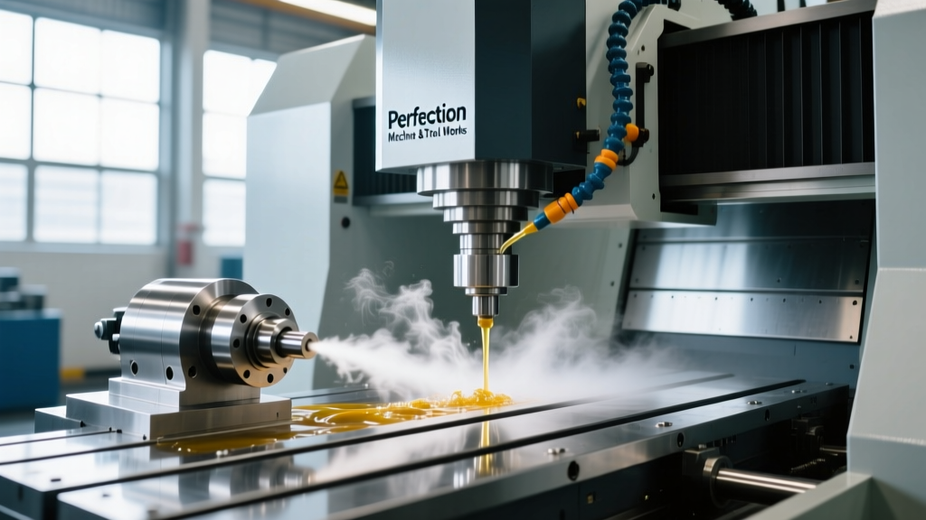
In oil-air systems, a micro-pump injects precise droplets (typically 0.05cc to 0.1cc per cycle) into a compressed air stream. The air carries the oil to the bearing raceway while simultaneously purging contaminants and providing mild evaporative cooling. The air supply must be rigorously dried to a dew point of -40°C to prevent moisture ingress into the angular contact bearings, which would otherwise cause hydrogen-induced fatigue and raceway spalling.
The Perfection Machine & Tool Works Lubrication Schedule
Automated lubrication schedules are programmed directly into the machine tool's PLC (Programmable Logic Controller). The following matrix represents the optimized intervals and volumes utilized for a standard 5-axis VMC operating on a 24/7 production schedule.
| System Component | Fluid Specification | Delivery Method | PLC Cycle / Interval | Target ISO 4406 Cleanliness |
|---|---|---|---|---|
| Linear Ways & Ball Screws | ISO VG 68 Way Oil | Proportional Metering Injectors | 3 sec pump / 45 min dwell | 18/16/13 |
| High-Speed Spindle | ISO VG 10 Spindle Oil | Oil-Air Metering Unit | 0.1cc every 120 seconds | 15/13/10 |
| ZF Gearbox (if equipped) | ISO VG 150 Synthetic Gear Oil | Splash / Manual Fill | 6-Month Drain & Refill | N/A (Splash system) |
| Hydraulic Tool Clamp | ISO VG 46 Anti-Wear Hydraulic | Continuous Pressure Loop | Annual Flush & Change | 16/14/11 |
Proportional Metering Units: How the Hardware Works
The core of the way lubrication network relies on positive displacement injectors (PDIs), such as those manufactured by Bijur Delimon. Unlike restrictive metering valves, PDIs provide a positive hydraulic lock that ensures every single metering pin actuates before the system pressure decays.
- Pressurization Phase: The PLC triggers the 120V AC pump motor. System pressure rapidly builds to 150 PSI. The metering pins are forced upward, displacing a fixed volume of oil (e.g., 0.06cc per pin) directly into the way channels.
- Monitoring Phase: A pressure switch monitors the manifold. If a line is broken, pressure will not reach the 150 PSI threshold within the 8-second timeout window, triggering an immediate feed-hold alarm on the CNC controller.
- Venting Phase: The pump motor stops, and an internal vent valve drops system pressure to 0 PSI. This allows the internal springs in the metering pins to reset for the next cycle.
Troubleshooting Lubrication-Induced Machining Errors
When geometric errors appear in machined parts, operators often blame tooling or CAM programming. However, root-cause analysis frequently points back to fluid film breakdown. Below is a diagnostic framework for identifying lubrication-related deviations.
Symptom: Circular Interpolation Axes Mismatch (Quadrant Glitches)
The Physics: When machining a perfect circle, the X and Y axes must smoothly transition through zero velocity at the quadrant points. If the way lubricant film is too thin, or if the tackifier has sheared, static friction spikes. The axis drive motor must 'wind up' torsionally to break the static friction, resulting in a visible 0.0002-inch to 0.0005-inch overshoot mark on the workpiece surface.
Corrective Action: Verify the physical actuation of the metering pins on the affected axis. Check the way oil viscosity using ASTM D445 kinematic viscosity testing. If the oil has been contaminated with solvent-based cleaning agents used during machine maintenance, the viscosity will drop, destroying the hydrodynamic wedge. Drain, flush with ISO VG 32 flushing oil, and refill with fresh ISO VG 68 way oil.
Symptom: Spindle Thermal Runaway Alarm at High RPM
The Physics: In oil-air systems, the compressed air acts as the primary cooling medium. If the shop's compressed air dryer fails and moisture enters the spindle, the oil emulsifies. Emulsified oil cannot maintain the elastohydrodynamic lubrication (EHL) film required between the ceramic bearing balls and steel races. Friction increases exponentially, causing the spindle chiller to max out its cooling capacity and trigger a thermal alarm.
Corrective Action: Install a coalescing filter and desiccant dryer inline immediately before the oil-air mixer. Verify the air line dew point is below -20°C. Purge the spindle oil lines by running the mixer at maximum cycle rate for 10 minutes while the spindle is stationary to flush out emulsified fluid.
Advanced Fluid Monitoring and Shop Integration
Maintaining these systems requires moving beyond reactive top-offs to predictive fluid analysis. Top-tier machine shops integrate inline particle counters on their hydraulic clamping circuits to monitor ISO 4406 cleanliness codes in real-time. A shift from a 16/14/11 code to an 18/16/13 code indicates a failing breather cap or a degrading pump seal, allowing maintenance teams to replace a $40 filter element before a $15,000 hydraulic pump suffers catastrophic cavitation.
Furthermore, way oil sump levels are increasingly monitored via capacitive level sensors tied directly to the shop's IoT dashboard. By tracking the exact rate of way oil consumption per machine hour, facility managers can identify failing wiper seals on the linear guides. A 15% increase in way oil consumption over a two-week baseline is a definitive indicator that the polyurethane way covers are degrading and allowing fluid to escape onto the shop floor, necessitating immediate seal replacement before coolant ingress contaminates the way system.