Machine Tool Industry News December 2025: Workholding Safety
Review machine tool industry news December 2025 regarding workholding safety, focusing on ANSI B11.8 compliance, chuck RPM limits, and vise torque specs.
The December 2025 Workholding Compliance Shift
Recent machine tool industry news December 2025 highlighted a significant regulatory pivot targeting workholding failures on the shop floor. Following a spike in reported near-misses involving lathe chuck jaw ejections and milling fixture pull-outs, OSHA and the ANSI B11 committee released updated enforcement guidelines. These updates specifically target the intersection of high-speed machining and workholding physics, demanding stricter adherence to clamping force retention metrics and T-slot torque specifications.
For machine shop managers and manufacturing engineers, compliance is no longer just about installing polycarbonate shields; it requires verifiable data on workholding limits. According to the OSHA 1910.212 General Requirements for All Machines, workholding devices must be capable of restraining the part against all anticipated cutting forces without relying solely on operator judgment. This article breaks down the specific technical requirements for vises, chucks, and custom fixtures to ensure your shop meets the new 2026 audit standards.
Lathe Chuck Safety: Mitigating Centrifugal Force Loss
The most critical safety vulnerability in CNC turning is centrifugal force loss in wedge-type chucks. As spindle RPM increases, the master jaws are pulled outward. This outward pull directly counteracts the hydraulic or manual drawbar force pushing the wedge inward, resulting in a severe drop in clamping force.
For example, a standard 10-inch wedge chuck (such as the Kitagawa BB-200) generating 18,000 lbs of static clamping force at 0 RPM will lose approximately 45% of its grip at 3,000 RPM. If the operator programs the spindle speed without calculating this loss, the part can slip or eject mid-cut.
CRITICAL SAFETY WARNING: Never rely on static clamping force ratings for high-speed turning. Always consult the manufacturer's dynamic clamping force graph. If your operation requires high RPM and heavy cuts, you must transition from standard wedge chucks to counter-centrifugal (CC) models.Standard Wedge vs. Counter-Centrifugal Chucks
Counter-centrifugal chucks utilize internal counterweights that move inward as the spindle speed increases, mechanically compensating for the outward pull of the master jaws. Below is a comparison of clamping force retention based on chuck design.
| Chuck Type | Static Force (0 RPM) | Force at 2,000 RPM | Force at 3,500 RPM |
|---|---|---|---|
| Standard Wedge (10-inch) | 18,000 lbs | 13,500 lbs (25% loss) | 8,100 lbs (55% loss) |
| Counter-Centrifugal (10-inch) | 16,500 lbs | 15,800 lbs (4% loss) | 14,900 lbs (9% loss) |
Note: Counter-centrifugal designs sacrifice a small amount of static clamping force to maintain dynamic stability. Always size your CC chuck based on the dynamic RPM requirement of your specific part geometry.
Milling Vise Compliance and T-Slot Failure Modes
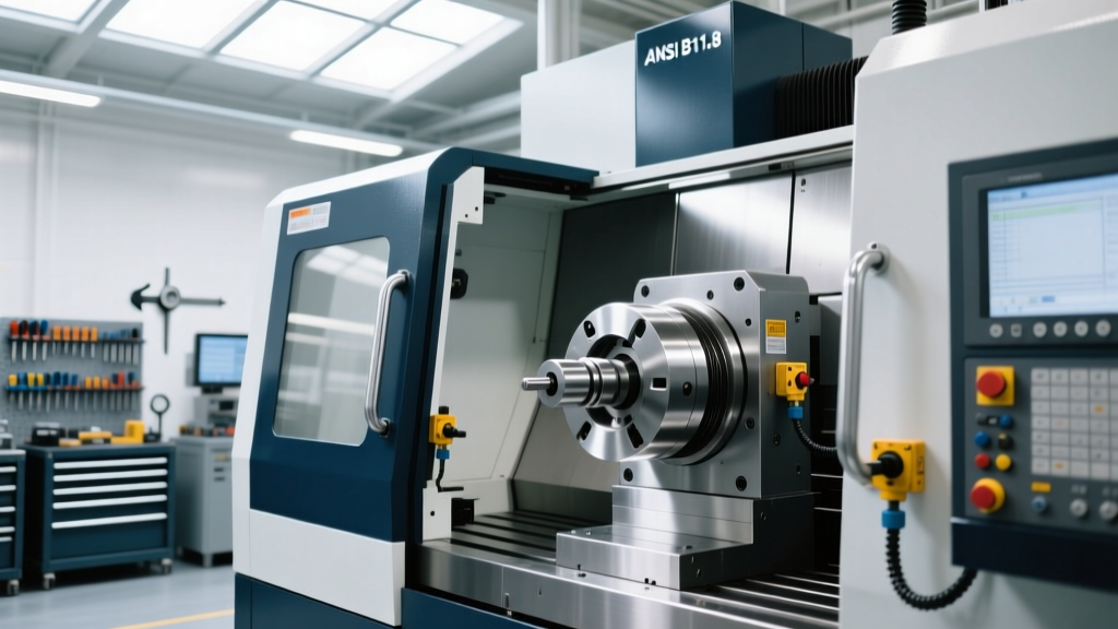
Under the ANSI B11.8 Safety Requirements for Milling Machines, workholding on vertical and horizontal machining centers must resist both vertical lifting forces and horizontal shear forces. The industry standard Kurt DX6 and DXS6 vises utilize the Anglock mechanism, which pulls the movable jaw downward and inward to counteract vertical lifting. However, the vise is only as secure as its connection to the machine table.
T-Slot Bolt Torque and Grade Specifications
A recurring failure mode identified in recent safety audits is the use of under-grade T-slot bolts or improper torque application. When a heavy roughing cut (e.g., 1-inch depth of cut in titanium) generates 2,500 lbs of lateral force, an under-torqued bolt will stretch, allowing the vise to shift.
- 5/8"-11 T-Slot Bolts: Must be Grade 8 (SAE) or ISO 10.9. Required torque: 90 to 110 ft-lbs.
- 1/2"-13 T-Slot Bolts: Must be Grade 8 or ISO 10.9. Required torque: 45 to 55 ft-lbs.
- 3/4"-10 T-Slot Bolts: Must be Grade 8 or ISO 10.9. Required torque: 160 to 180 ft-lbs.
Shops must implement calibrated torque wrenches at every setup station. Relying on an operator pulling a standard hex key with a cheater bar is a direct violation of OSHA machine guarding protocols regarding secure workholding.
Hydraulic Clamping Interlocks and Pressure Thresholds
For shops utilizing hydraulic pallet systems or automated tombstones, compliance requires failsafe interlocks. If a hydraulic pump fails or a hose bursts mid-cycle, the clamping pressure drops, and the spinning cutter will rip the part from the fixture.
Compliant systems must integrate a pressure switch tied directly to the CNC controller's M-code sequence. The standard operational logic must be:
- Operator initiates clamping (M10).
- Hydraulic system reaches target pressure (e.g., 3,000 PSI).
- Pressure switch closes, sending a 24V signal to the PLC.
- PLC verifies pressure is above the 2,500 PSI safety threshold.
- Spindle start enable is granted.
If pressure drops below 2,500 PSI during the cut, the PLC must immediately trigger an E-Stop or feed-halt, overriding the part program. Shops running older hydraulic units without digital pressure feedback must retrofit analog pressure switches to meet 2026 compliance standards.
Custom Fixtures: Shear Pins and Factor of Safety (FoS)
When designing custom weldment fixtures or modular tombstones, engineers often rely entirely on the friction generated by hydraulic clamps to hold the part. This is a critical design flaw. Friction coefficients vary wildly based on coolant contamination, surface finish, and material hardness.
"Never design a fixture where clamping friction is the sole restraint against primary cutting forces. Always incorporate positive mechanical stops or shear pins to absorb dynamic loads." — Manufacturing Engineering Best Practices, SME.
For heavy-duty custom fixtures, incorporate hardened dowel pins (minimum 0.500" diameter, hardened to 60 HRC) positioned directly behind the primary cutting force vector. The design Factor of Safety (FoS) for static fixture components should be a minimum of 3:1, while dynamic components subject to high-frequency vibration (such as those in aerospace titanium milling) require a 5:1 FoS to prevent fatigue cracking in the fixture body.
2026 Shop Floor Workholding Audit Checklist
To ensure compliance with the latest OSHA and ANSI directives, facility managers should execute the following audit protocol on all manual and CNC equipment:
- Chuck RPM Tags: Verify every lathe chuck has a visible, legible tag stating the exact maximum safe RPM based on the heaviest jaw set currently in use.
- Jaw Serration Inspection: Inspect 60-degree and 90-degree jaw serrations for wear. Worn serrations reduce grip force by up to 30% and increase the risk of part slippage under heavy interrupted cuts.
- T-Slot Bolt Inventory: Remove all Grade 5 or unmarked T-slot bolts from the shop floor. Replace exclusively with Grade 8 / ISO 10.9 hardware.
- Hydraulic Interlock Test: Manually drop hydraulic pressure on all automated fixtures while the machine is in cycle to verify the spindle halts immediately.
- Vise Rebuild Schedule: Disassemble and inspect Kurt Anglock vises every 1,500 operating hours. Replace worn spherical segments and re-grease with high-moly lithium complex grease to maintain full downward clamping vector.
By treating workholding as a critical safety system rather than a simple consumable tool, shops can eliminate catastrophic ejections, protect operators, and pass rigorous regulatory audits. For further guidance on machine guarding and hazard prevention, consult the OSHA Machine Guarding eTool to evaluate your specific equipment configurations.