Mastering Trevisan Machine Tool Safety Interlocks and E-Stops
Master Trevisan machine tool safety interlocks and E-stop protocols. Learn operator best practices for heavy-duty CNC lathes and drills.
The Kinetic Reality of Trevisan Heavy-Duty Machining
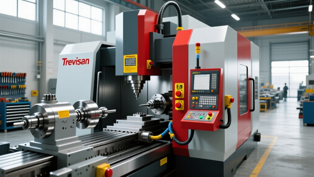
Trevisan Macchine Utensili manufactures some of the most formidable heavy-duty CNC lathes, deep-hole drilling systems, and valve machining centers in the global market. These machines are engineered for the oil, gas, and energy sectors, routinely handling massive, asymmetric workpieces. When a 1,500mm four-jaw chuck rotates a 4-ton oilfield valve body at 250 RPM, the stored kinetic energy is staggering. In this environment, safety interlocks and emergency stop (E-stop) systems are not mere regulatory checkboxes; they are critical survival mechanisms designed to manage extreme mechanical inertia.
Operator training on Trevisan equipment must transcend basic button-pushing. It requires a fundamental understanding of how the machine's safety programmable logic controller (PLC) manages high-torque braking, guard locking, and fault diagnostics. This guide details the specific interlock architectures used on heavy-duty Trevisan machines and provides actionable best practices for operators and maintenance teams.
Interlock Architecture: Matching the Switch to the Hazard
Heavy-duty machine tools utilize a hierarchy of interlocking devices based on the specific hazard zone's risk assessment. According to UK Health and Safety Executive (HSE) guidelines on machinery interlocks, the choice of device must account for stopping time, guard opening frequency, and the environment. On Trevisan machines, the harsh environment of high-pressure coolant and heavy metal swarf dictates the use of industrial-grade, sealed switching technologies.
| Interlock Type | Common Technology | Typical Trevisan Application | Operating Principle |
|---|---|---|---|
| Solenoid Guard Lock | Schmersal AZM400 / Euchner STA | Main Spindle Enclosures, Chuck Guards | Power-to-Unlock: Guard remains mechanically locked until the PLC confirms 'Safe Zero Speed' via spindle encoder feedback. |
| RFID Non-Contact | Sick TR10 / Euchner CES | Chip Conveyor Doors, Coolant Tank Hatches | Coded magnetic/RFID field detects actuator. Immune to metallic swarf buildup that defeats mechanical limit switches. |
| Trapped Key Systems | Fortress AmKey / Castell | Deep-Hole Drill Coolant Manifolds, High-Voltage Cabinets | Physical key exchange ensures power is isolated before a secondary access door can be unlocked. |
The most common safety violation on heavy CNC lathes is the use of a 'cheat key' or a spare RFID actuator taped to the machine frame to bypass guard interlocks during setup. On a Trevisan lathe, bypassing a chuck guard interlock while the spindle is in jog mode exposes the operator to severe entanglement hazards from rotating jaws and uneven workpiece geometries. Strict disciplinary policies and daily actuator audits are mandatory.
Emergency Stop (E-Stop) Logic: Category 0 vs. Category 1
Operators often assume that hitting an E-stop instantly cuts all power to the machine. On heavy-duty equipment, this is not only incorrect but mechanically dangerous. Trevisan machines utilize advanced safety PLCs (typically Siemens SIMATIC S7-1500F series) to execute different stop categories based on ISO 13849-1 standards.
Category 1 Stop: The Spindle Deceleration Protocol
When an E-stop is triggered on the main operator pendant, the Trevisan spindle does not immediately lose power. A Category 0 stop (immediate power removal) on a 2-ton rotating workpiece would cause catastrophic mechanical shock to the main gearbox, shear drive keys, and potentially cause the workpiece to break free from the chuck jaws due to sudden inertial torque.
Instead, the safety PLC initiates a Category 1 stop:
- Dynamic Braking: The Variable Frequency Drive (VFD) immediately commands maximum braking torque, feeding kinetic energy back into the DC bus or dissipation resistors.
- Zero-Speed Verification: The safety PLC monitors the spindle encoder. Once the RPM drops below a safe threshold (usually < 10 RPM), the mechanical spindle brake is engaged.
- Power Removal: Only after the mechanical brake is confirmed engaged and the spindle is fully stopped do the main safety contactors drop, physically removing power from the VFD and spindle motor.
Category 0 Stop: Auxiliary Systems
Conversely, auxiliary systems with low inertia—such as high-pressure coolant pumps, hydraulic power units, and chip conveyors—receive a Category 0 stop. Power is removed instantaneously via safety relays to halt fluid flow and mechanical movement immediately.
Operator Training: Daily Shift-Start Verification Protocol
Relying solely on maintenance to verify safety systems is a critical operational flaw. Operators must perform a functional safety check at the start of every shift. This 5-minute routine ensures the dual-channel safety circuits are intact and no interlocks have been compromised.
- Visual Guard Inspection: Inspect all polycarbonate and steel guard windows for deep gouging or coolant-induced crazing. Ensure no heavy swarf is wedged in the guard door hinges, which can cause sagging and misalign RFID actuators.
- The 'Open-Door' Run Test: With the machine in a safe, unclamped state, close the main chuck guard and initiate a low-speed spindle rotation (e.g., 20 RPM in MDI). Carefully open the guard door by a fraction of an inch. The spindle must immediately initiate a Category 1 stop. If it continues to rotate, lock out the machine and report the fault.
- E-Stop Circuit Validation: Press the primary E-stop button on the operator panel. Verify on the HMI that the safety PLC registers the fault and that the main hydraulic pump contactors physically click open.
- Solenoid Lock Check: Attempt to pull the main chuck guard handle while the spindle is completely stopped but the machine is still in 'Cycle Ready' mode. The solenoid should resist opening. Only when the HMI indicates 'Guard Unlock Permitted' should the handle move freely.
Troubleshooting Intermittent Safety Faults
Heavy machining environments cause vibration, thermal expansion, and physical impacts that degrade safety hardware over time. When a Trevisan machine faults out with a safety alarm, operators and setup technicians can use this decision tree to isolate the issue before calling maintenance.
Symptom: HMI Displays 'Chuck Guard Open' When Door is Physically Closed
- Cause 1: Actuator Misalignment. Heavy steel doors sag over time due to hinge wear. The RFID actuator may have dropped below the sensor's reading window (typically a strict ±3mm tolerance). Fix: Shim the hinge or adjust the sensor bracket.
- Cause 2: Swarf Interference. Fine cast-iron or steel dust mixed with coolant can form a hardened crust over the RFID sensor face. Fix: Wipe the sensor face with a non-abrasive cloth and isopropyl alcohol.
- Cause 3: Dual-Channel Mismatch. Safety switches use two independent circuits (OSSD1 and OSSD2). If one wire is pinched or corroded, the safety PLC detects a mismatch and defaults to a safe state. Fix: Requires a multimeter continuity check by maintenance.
Symptom: Solenoid Guard Will Not Unlock After Spindle Stops
- Cause 1: Encoder Drift. The safety PLC relies on the spindle encoder to confirm zero speed. If the encoder coupling is loose, the PLC may read 2-3 RPM of 'drift' and refuse to release the solenoid lock. Fix: Maintenance must inspect the encoder coupling.
- Cause 2: Solenoid Plunger Binding. High-pressure coolant mist can penetrate the solenoid housing, causing internal corrosion that prevents the plunger from retracting, even when energized. Fix: Replace the solenoid lock assembly; do not attempt to force the door open with a pry bar, as this will destroy the locking mechanism.
Compliance and the Human Element
Adherence to OSHA standard 1910.212 (General Requirements for All Machines) mandates that guards and interlocks be secured and not easily bypassed. However, regulatory compliance is only half the battle. The true safety margin on a Trevisan machine tool is defined by the operator's respect for the physics involved.
Training programs must explicitly demonstrate the kinetic energy calculations of the specific workpieces being machined. When an operator understands that a sudden E-stop on a 6-ton rotor generates enough torsional force to snap a 100mm steel boring bar, they are far less likely to bypass a solenoid lock to 'save a few seconds' during a setup change. Integrating these engineering realities into daily operator training transforms safety interlocks from an annoying operational hurdle into a deeply respected lifeline.