Mastering DRO Readouts in Tool Steel Machining Operations
Learn operator best practices for DRO calibration, scale selection, and thermal compensation to maintain tight tolerances in tool steel machining.
The Thermal and Mechanical Reality of Tool Steel
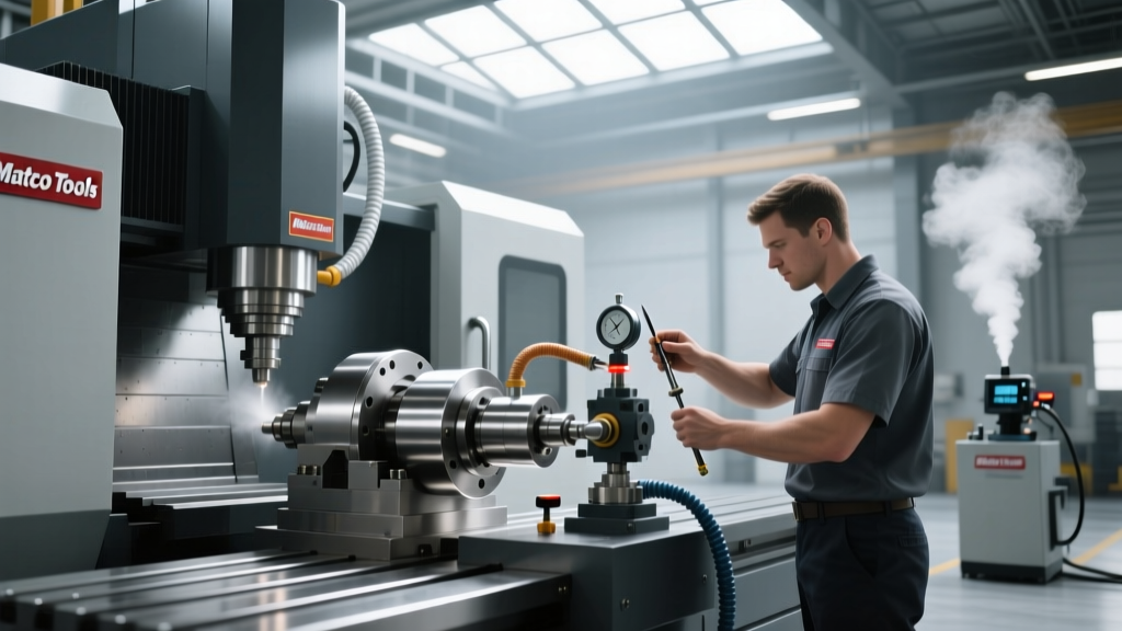
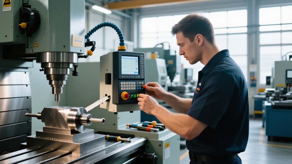
Tool steel machining—specifically working with high-carbon, high-chromium grades like D2, air-hardening A2, and high-speed M2—generates immense cutting forces and localized thermal loads. When operators rely on Digital Read Out (DRO) systems on manual or semi-CNC knee mills and lathes, a fundamental misunderstanding often leads to scrapped parts: the DRO measures the machine table position, not the workpiece dimension.
During heavy roughing of D2 tool steel, localized workpiece temperatures can easily exceed 60°C. The coefficient of thermal expansion (CTE) for D2 is approximately 10.4 µm/m·°C. If an operator is machining a 400mm long die block and the part experiences a 30°C temperature rise above the standard 20°C metrology baseline, the steel expands by roughly 0.124mm. If the operator machines to the exact DRO readout without accounting for this thermal growth, the part will shrink below tolerance once it cools to room temperature. Mastering DRO readouts requires operators to synthesize machine positioning data with real-time material physics.
CRITICAL WARNING: Coolant Temperature VarianceIn 2026, many shops still flood-machine tool steel with unchilled water-soluble coolants. If your coolant tank is at 28°C and the shop ambient temperature is 20°C, you are actively heating the workpiece and the machine casting. Always verify coolant temperature before trusting DRO offsets on tight-tolerance (+/- 0.01mm) tool steel operations.
Selecting the Right DRO Scale Technology for Hard Materials
Not all linear encoders survive the harsh environment of tool steel machining. Milling M2 or D2 produces fine, abrasive carbide dust and requires heavy, high-pressure coolant splash to evacuate chips. Selecting the wrong scale technology guarantees premature failure and skipped counts.
| Scale Technology | Brand / Model Example | Tool Steel Suitability | Est. Cost (400mm) |
|---|---|---|---|
| Optical Glass | Heidenhain LS Series | Poor. Fine D2 carbide dust causes stiction and optical reader blockages. Requires pristine bellows. | $650 - $850 |
| Magnetic | Sony Magnescale | Fair. Resists coolant, but heavy interrupted cuts in pre-hardened tool steel can cause vibration-induced count skipping. | $350 - $450 |
| Inductive | Newall Spherosyn | Excellent. Immune to coolant, oil, and abrasive dust. Handles high-vibration interrupted cuts without losing position. | $450 - $550 |
For dedicated tool steel machining on manual Bridgeport-style mills or heavy bed lathes, inductive scales are the mandatory choice. As detailed in Heidenhain's digital readout systems documentation, while optical scales offer sub-micron resolution for jig grinders, the sealed inductive design of systems like the Newall Spherosyn provides the 5µm resolution and extreme environmental IP67 protection required for dirty, high-vibration roughing and semi-finishing operations.
Operator Training: Compensating for Deflection and Sag
Tool steel requires high rigidity. When an operator takes a 0.150" (3.8mm) depth of cut in A2 tool steel with a 3/4" solid carbide endmill, the cutting forces will physically deflect the machine quill and stretch the column. The DRO will read the exact Z-axis position of the knee or quill, but the tool tip will be pushed upward by the cutting forces.
Step-by-Step Deflection Offset Protocol
- Establish the Baseline: Take a light finishing pass (0.005" DOC) at the final feed rate. Measure the part with a calibrated micrometer. Set this as your absolute Z-zero.
- Map the Deflection: Take a roughing pass at your maximum DOC (e.g., 0.150"). Stop the machine without moving the Z-axis handwheel. The DRO reads Z -0.1500". However, due to quill deflection, the actual cut depth might only be 0.142".
- Program the Offset: Modern 2026 DRO interfaces allow operators to input a 'Tool Deflection' or 'Backlash' offset specifically for the Z-axis. Input the 0.008" variance into the DRO's offset menu so the display reflects the actual tool tip position under load, not just the quill casting position.
- Verify with Spark-Out: Always perform a zero-DOC spark-out pass on the final dimension to eliminate elastic recovery errors in the tool steel itself.
If your DRO Z-axis scale is mounted to the exterior of the ram, it will not read quill extension sag. When extending the quill past 3 inches to reach deep into a D2 die shoe, the weight of the quill assembly causes a negative Z-axis drift of up to 0.002". Operators must lock the quill and move the knee for all final Z-axis depth sizing in tool steel.
Edge Case: Interrupted Cuts and Scale Vibration
Tool steel machining frequently involves interrupted cuts—milling across keyways, cross-holes, or uneven forged surfaces. These impacts generate high-frequency shockwaves through the machine table. Magnetic and optical scales rely on delicate reading heads that can 'skip' or miscount pulses when subjected to shock loads exceeding 3g to 5g. Inductive scales utilize a continuous coil and ferromagnetic ball bearing chain, allowing them to withstand shock loads up to 15g without losing absolute position. Operators must be trained to recognize the acoustic signature of a skipped count: a sudden change in the harmonic pitch of the cut, indicating the tool has engaged more material than the DRO is currently displaying.
"When machining pre-hardened M2 high-speed steel, the intermittent shock loads of an interrupted cut will destroy the glass wipers on optical scales in under three months. We switched entirely to inductive encoders and reduced our DRO-related scrap rate by 14% in the first year."
— Master Machinist, Aerospace Die & Mold Division
Troubleshooting DRO Drift During Heavy Roughing
Even with the correct scale technology, operators must know how to diagnose readout anomalies mid-shift. Use this decision matrix when the DRO display conflicts with physical part measurements.
| Symptom | Root Cause in Tool Steel Ops | Corrective Action |
|---|---|---|
| X/Y Axis display jumps erratically | Swelling of machine way wipers pushing debris against the scale housing, causing micro-binding. | Clean scale housing; adjust way wiper tension; verify scale mounting brackets are not torqued to the point of twisting the encoder tube. |
| Z-Axis creeps downward when locked | Quill lock is worn; heavy tool steel cutting forces are pulling the spindle down against the DRO scale. | Rebuild quill lock mechanism. Never rely on the quill lock for heavy D2 roughing; use the knee lock and Z-axis knee scale instead. |
| Consistent dimensional error on one axis | Pitch error in the ball screw or thermal expansion of the machine casting, not the DRO scale. | Run a dial indicator test over 12 inches. Input the pitch error compensation map into the DRO controller memory. |
Pitch Error Compensation and Metrology Standards
According to ISO 230-2 standards for machine tool accuracy, manual machines equipped with DROs are still subject to the mechanical inaccuracies of their lead screws. When machining tool steel, where tolerances are frequently held to +/- 0.0005" (0.012mm), the inherent pitch error of a standard Acme or even a worn ball screw will result in out-of-tolerance parts. Operators must be trained to use the DRO's Pitch Error Compensation (PEC) feature. By mapping the axis with a laser interferometer or a high-precision linear encoder and inputting the deviation data into the DRO head (such as a 3-axis display unit), the readout will automatically add or subtract the mechanical error from the displayed value, providing true tool-tip positioning.
Shift Handoff Checklist for Tool Steel DRO Operations
To maintain continuity and prevent scrap across multi-shift tool steel machining operations, implement this mandatory DRO verification checklist at every shift change:
- Thermal Equilibrium Check: Verify spindle and coolant temperatures. If the machine was idle for more than 4 hours, run a 15-minute thermal soak cycle before trusting Z-axis offsets.
- Scale Wiper Inspection: Visually inspect the inductive or magnetic scale wipers for packed D2/M2 carbide sludge. Clean with isopropyl alcohol, never with compressed air which forces debris into the reader head.
- Absolute Zero Verification: Re-sweep the primary datum edge with a 0.0001" test indicator to ensure the X/Y absolute zero has not drifted due to table lock slippage during heavy climb milling.
- Offset Audit: Review all active tool radius and Z-deflection offsets in the DRO memory to ensure the previous operator did not leave 'scratch' offsets active.
By treating the DRO not just as a digital ruler, but as a dynamic compensation system that accounts for thermal expansion, mechanical deflection, and material-specific shock loads, operators can consistently hold tight tolerances in the most demanding tool steel machining applications.