Maintaining Calibration Accuracy During Machine Tool Tending
Discover how automated machine tool tending impacts ISO 230 calibration accuracy. Learn exact maintenance schedules, diagnostic steps, and drift fixes.
The Physics of Tending-Induced Geometric Drift
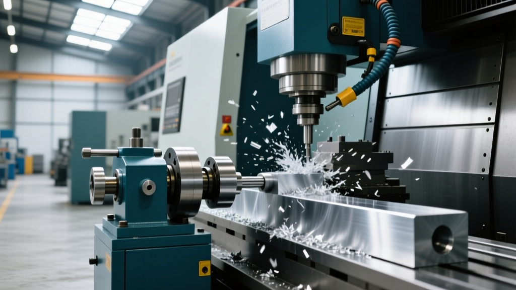
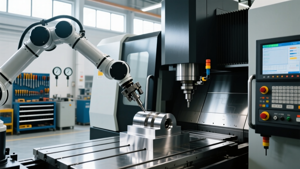
Automated machine tool tending transforms a standalone CNC mill or lathe into a high-throughput manufacturing cell, but it fundamentally alters the machine's kinematic and thermal baseline. When a robotic arm—such as the 180 kg FANUC M-20iD/25—mounts directly to the machine enclosure or operates in tight proximity, the dynamic forces of part loading, automated door actuation, and gripper seating introduce micro-deflections. These mechanical stresses and thermal loads create geometric drift that standard, standalone annual calibration schedules completely fail to capture.
Machine tool accuracy standards, primarily governed by the ISO 230 series, assume a relatively static environmental and mechanical baseline. However, a tended machine experiences cyclical impact loads every time a gripper seats a workpiece into a hydraulic vise or tombstone fixture. If the pneumatic seating force exceeds 400 N, or if the robotic TCP (Tool Center Point) is misaligned by even 0.05 mm, the resulting lateral sheer forces can induce temporary X and Y-axis yaw errors. Over a 24/7 production schedule, these cyclic loads accelerate ballscrew wear and compromise the volumetric accuracy of the machine tool.
WARNING: Never perform a standard ISO 230 ballbar test while the automated tending system is in its 'home' or 'parked' position. The static mass of the robotic arm parked on the machine pallet or enclosure skews the baseline geometric data, masking up to 8 µm of X-axis sag and leading to incorrect CNC controller compensation values.ISO 230 Standards and the Tending Cell Reality
To maintain compliance and precision in automated cells, maintenance teams must look beyond basic geometric testing. According to the ISO 230-1:2022 standard for machine tool test conditions, geometric accuracy of machines operating under static conditions must account for external load influences. In a tended environment, this means evaluating the machine under the simulated load of the tending system's maximum payload and peak dynamic forces.
Furthermore, research from the NIST Machine Tool Metrology group highlights that volumetric error compensation (VEC) is critical for multi-axis cells. Standalone machines might rely on 1D laser interferometry for pitch and yaw, but a tended 5-axis machine requires full 3D spatial mapping. The physical presence of the tending robot restricts the line-of-sight required for traditional laser tracker setups, necessitating the use of wireless telemetry and specialized fixturing to capture the machine's true working envelope while the robot is active.
"In automated tending cells, the machine tool and the robot are not two separate entities; they are a single coupled kinematic chain. Calibrating the CNC without accounting for the robot's thermal and mechanical footprint is an exercise in futility." — Advanced Manufacturing Metrology Guidelines.
Calibration Tooling & Frequency Matrix for Tended Cells
Standard maintenance intervals are insufficient for automated cells. The following matrix outlines the specific metrology equipment required, realistic 2026 market pricing, and the adjusted frequencies necessary to maintain sub-15 µm volumetric accuracy in a tended environment.
| Metrology Tool | Primary Application in Tending Cell | Est. Cost (2026) | Required Frequency |
|---|---|---|---|
| Renishaw QC20-W Wireless Ballbar | Circular interpolation errors, backlash, and servo mismatch isolated from robot vibration. | $18,500 - $22,000 | Quarterly |
| API Radian Laser Tracker | Full Volumetric Error Compensation (VEC) mapping of the CNC and robot handoff zones. | $95,000 - $120,000 | Annually |
| Heidenhain Kinelog / Spindle Probes | Continuous thermal drift mapping and automated work offset updates post-gripper loading. | Integrated ($4,500 add-on) | Continuous / Daily |
| Calibrated Master Artifact (Tombstone) | Verifying robot-to-machine TCP handoff accuracy and fixture seating repeatability. | $2,500 - $5,000 | Monthly |
Step-by-Step Diagnostic for Gripper Seating Deflection
When a tended machine begins producing out-of-tolerance parts—specifically showing position errors that correlate with the automated loading sequence—the root cause is often gripper seating deflection. Follow this diagnostic sequence to isolate the error.
Step 1: Isolate End-Effector Kinematics
Before blaming the CNC axis geometry, verify the tending arm's end-effector. Mount a 0.001 mm resolution Dial Test Indicator (DTI) to the machine spindle. Jog the spindle to touch the DTI plunger against the flat datum surface of the robotic gripper while the robot is holding a part in the loading zone. Command the robot to execute its standard seating routine. If the DTI needle fluctuates by more than 0.015 mm during the seating cycle, the robot's approach vector is incorrect, or the gripper fingers are worn. Recalibrate the robot's TCP and replace the gripper contact pads with high-durometer polyurethane to absorb impact shock.
Step 2: Map Thermal Asymmetry from Servo Brakes
Robotic arms generate significant heat in their joint servo brakes, particularly the J2 and J3 axes which support the arm's cantilevered mass. If the robot parks within 400 mm of the machine's spindle headstock or column, radiant heat will cause localized thermal expansion. Use a spindle probe to measure a fixed internal machine datum at the start of the shift, and again after 4 hours of continuous tending. Expect to see 12 to 18 µm of Z-axis growth solely from the robot's thermal footprint. If confirmed, reprogram the robot's 'home' position to park further away from the machine column, or install a localized thermal barrier shield.
Step 3: Execute Loaded Diagonal Tests (ISO 230-6)
Standard ballbar tests only measure 2D circular planes. To capture the Z-axis sag induced by the heavy automated door opening and the momentum of the tending arm entering the workspace, perform an ISO 230-6 diagonal test. Program the machine to execute rapid diagonal traverses (X, Y, and Z moving simultaneously) while the tending robot mimics its loading cycle outside the machine. Use a laser interferometer to track the diagonal path. This reveals dynamic following errors that only occur when the machine and robot are operating in synchronized, high-speed motion.
The 2026 Maintenance Schedule for Tended CNC Cells
To maintain peak accuracy and prevent catastrophic collisions between the tending robot and the machine tool, implement this strict, tiered maintenance schedule. This goes far beyond standard CNC lubrication checks.
- Daily: Pneumatic Seating Force Verification. Check the air pressure regulators on the robotic gripper. The seating pressure must hold strictly at 6.0 bar ± 0.1 bar. Drops in pressure lead to incomplete part seating in the vise, causing the CNC machine to cut parts based on a false Z-axis datum, resulting in scrap.
- Weekly: Fixture Datum and Tombstone Inspection. Automated loading impacts cause micro-galling on fixture datums. Inspect the hardened steel locating pins and rest buttons on the tombstone. Use a portable surface roughness tester; if the Ra value of the locating surface exceeds 0.8 µm, polish or replace the buttons to prevent part misalignment.
- Monthly: Robot-to-Machine TCP Handoff Audit. Run a calibrated master artifact through the automated loading cycle. Once seated, use the CNC machine's Renishaw OMP60 spindle probe to measure the artifact's X, Y, and Z position. Compare these values against the robot's internal positional feedback. If the delta exceeds 0.03 mm, execute a full 6-axis robot kinematic calibration (using tools like FANUC's iRCalibration).
- Quarterly: Wireless Ballbar Testing. Perform a Renishaw QC20-W wireless ballbar test on the CNC machine. Crucially, the test must be run with the automated doors cycling open and closed to simulate real-world production drag and vibration. Update the CNC controller's backlash and pitch error compensation tables based on the generated diagnostic report.
- Annually: Volumetric Error Compensation (VEC) & Leveling. Hire a certified metrology service to perform a full 21-error-parameter VEC map using a laser tracker. Automated cells experience foundation settling and floor vibration differently than standalone machines due to the combined mass and dynamic forces. Re-level the machine and robot baseplate using precision machinist levels (0.02 mm/m resolution) and inject epoxy grout under the leveling pads if voids have developed.
Integrating Metrology into the Cell Controller
The most advanced machine shops in 2026 are moving away from manual calibration schedules and integrating metrology directly into the cell's PLC (Programmable Logic Controller). By utilizing macro-driven probing routines immediately after the tending robot loads a part, the CNC machine can dynamically update its work offsets (G54-G59) in real-time. This closed-loop system compensates for minor seating variations and thermal drift on a per-part basis, effectively masking the geometric inaccuracies introduced by the automated tending process. However, this software-based compensation relies entirely on a mechanically sound baseline; it cannot fix worn ballscrews or loose robot baseplates. Rigorous adherence to the physical maintenance schedules outlined above remains the non-negotiable foundation of automated manufacturing accuracy.