Evaluating a List of Machine Tools: Linear vs Box Way Guide Systems
When reviewing a list of machine tools, understanding way systems is critical. Compare linear guideways and box ways for CNC milling and turning specs.
When engineering and procurement teams compile a list of machine tools for capital expenditure, the spindle taper, RPM, and CNC controller typically dominate the specification sheet. However, the true foundation of machining accuracy, surface finish, and long-term rigidity lies hidden beneath the sheet metal: the guideway system. Choosing between linear guideways and traditional box ways dictates the machine's dynamic response, vibration damping, and ultimate suitability for specific metallurgical applications.
This technical guide dissects the mechanical physics, friction coefficients, and failure modes of both way systems to provide a definitive decision framework for machine shop integration.
The Physics of Linear Guideways (Rolling Friction)
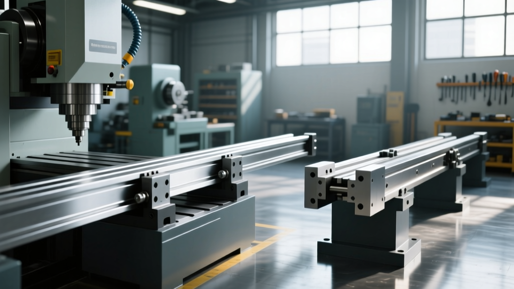
Linear guideways utilize recirculating ball or roller bearings trapped between a hardened steel rail and a carriage block. The core advantage is the transition from sliding friction to rolling friction, which fundamentally alters the machine's kinematic behavior.
Friction and the Stick-Slip Phenomenon
The coefficient of friction ($\mu$) in a properly preloaded linear guide is exceptionally low, typically ranging from 0.002 to 0.005. Because rolling friction is largely independent of velocity, linear guides virtually eliminate the "stick-slip" phenomenon at ultra-low feed rates. This makes them mandatory for high-speed contouring, micro-machining, and applications requiring simultaneous multi-axis interpolation at varying speeds.
Preload and Rigidity Mechanics
Rigidity in linear systems is achieved through preload—the intentional oversizing of the rolling elements to create negative internal clearance. According to technical data from THK Linear Motion Guides, preload is generally categorized into three classes:
- Light Preload (approx. 2% of dynamic load rating): Used for high-speed, low-load applications like aluminum aerospace structuring.
- Medium Preload (approx. 5%): The standard for general-purpose CNC vertical machining centers (VMCs).
- Heavy Preload (approx. 8-10%): Reserved for heavy-duty roller guideways (e.g., Rexroth BSHP series) where maximum moment-load rigidity is required, though it accelerates fatigue life consumption and increases heat generation.
Heavy preload generates significant friction heat at high traverse rates (e.g., >40 m/min). If the machine casting is not thermally symmetrical or lacks active chiller circuits for the lubrication system, the linear rails will expand, inducing geometric errors in the Y and Z axes. Modern high-end VMCs mitigate this by circulating temperature-controlled oil through the carriage blocks.
Box Way Architecture (Sliding & Hydrostatic Friction)
Box ways rely on large, flat sliding surfaces. The moving component (usually the saddle or column) slides directly against the stationary bed. To prevent catastrophic galling, the sliding surfaces are coated with low-friction polymers or separated by pressurized fluid films.
Turcite and PTFE Composites
Standard box ways utilize Turcite-B or similar PTFE/bronze composite liners bonded to the cast iron sliding surface, running against hardened and ground steel or cast iron mating surfaces. The friction coefficient is higher than linear guides, typically $\mu$ = 0.05 to 0.08. While this introduces mild stick-slip at feed rates below 5 mm/min, the massive surface area contact provides unparalleled vibration absorption.
Hydrostatic Box Ways: The Pinnacle of Damping
For ultra-precision and ultra-heavy cutting, hydrostatic box ways represent the apex of machine tool design. Pressurized oil (typically ISO VG 68 or VG 100) is pumped into precisely machined pockets on the sliding surface at pressures ranging from 300 to 1,500 PSI. This creates a microscopic fluid film (10 to 50 microns thick) that completely separates the metal surfaces.
"Hydrostatic way systems yield a friction coefficient near zero while maintaining the massive damping ratio of a box way. This allows machines to take 50mm depth-of-cut passes in titanium without chatter, a physical impossibility on rolling-element guides."
— Adapted from Society of Manufacturing Engineers (SME) technical papers on machine tool dynamics.
Technical Specification Matrix: Linear vs. Box Ways
The following matrix contrasts the quantifiable engineering specifications of both systems to aid in cross-referencing your list of machine tools against your production requirements.
| Parameter | Linear Guideways (Ball/Roller) | Box Ways (Turcite/Sliding) | Hydrostatic Box Ways |
|---|---|---|---|
| Friction Coefficient ($\mu$) | 0.002 - 0.005 | 0.05 - 0.08 | ~0.0001 (Fluid shear) |
| Damping Capacity | Low (1x baseline) | High (3x - 5x baseline) | Very High (5x - 8x baseline) |
| Max Traverse Speed | 60 - 120 m/min | 15 - 24 m/min | 10 - 20 m/min |
| Shock Load Resistance | Poor (Brinelling risk) | Excellent | Excellent |
| Maintenance Interval | Low (Auto-lube systems) | Medium (Way cover checks) | High (Filtration/Chiller) |
Real-World Failure Modes and Edge Cases
Understanding how these systems fail in production environments is critical when evaluating machine longevity and total cost of ownership.
Linear Guide Failure: Brinelling and Micro-Welding
Because linear guides rely on point or line contact, they are highly susceptible to Brinelling—permanent indentation of the raceway caused by shock loads. If a CNC mill takes an interrupted cut in hardened steel or experiences a crash, the impact force can exceed the static load rating of the bearings, leaving dents in the rail. This results in a distinct clicking noise during traversal and destroys surface finish. Furthermore, if the automatic lubrication line clogs, the lack of an oil film leads to micro-welding between the ball and raceway, causing catastrophic carriage seizure within minutes.
Box Way Failure: Scoring and Swarf Intrusion
Box ways fail primarily through scoring (deep scratches in the Turcite or cast iron). This occurs when way covers (bellows or telescopic steel shields) fail, allowing abrasive cast iron or Inconel swarf to embed in the soft Turcite liner. The embedded chips act like sandpaper, rapidly scoring the hardened mating rail. Unlike linear guides, box ways can often be scraped and re-Turcited in the field by a specialized rebuilder, whereas a brinelled linear rail must be entirely replaced.
Warning: Lubrication IncompatibilityNever use way oil (ISO VG 68 with tackifiers) in linear guide carriages unless explicitly specified by the OEM. The tackifiers can cause the recirculating ball end-caps to clog, starving the internal raceway. Linear guides typically require NLGI Grade 2 lithium-complex grease or specialized low-viscosity synthetic oils.
Decision Framework for Procurement
When filtering your list of machine tools, apply this binary decision matrix to select the correct way system for your specific production cell:
- Choose Linear Guideways IF:
- Your primary materials are aluminum, plastics, or non-ferrous alloys.
- You require high-speed 3D contouring (e.g., aerospace structural components or mold/die finishing).
- Traverse rates above 40 m/min are necessary to reduce non-cutting time.
- Reference Machines: Standard Haas VF series, DMG Mori NVX series.
- Choose Box Ways IF:
- You perform heavy roughing, interrupted cuts, or machine hard metals (Titanium, Inconel, tool steels).
- Chatter and harmonic vibration are limiting your tool life and insert costs.
- Your feed rates rarely exceed 15 m/min, prioritizing cutting force over traverse speed.
- Reference Machines: Kitamura Mycenter HX series (hardened box ways), Okuma GENOS series (depending on configuration).
The Hybrid Compromise
For shops requiring a balance of both worlds, some OEMs now offer hybrid configurations. For example, utilizing linear guides on the X and Y axes for rapid positioning and high-speed contouring, while employing a box way on the Z-axis to absorb the vertical shock loads of heavy plunge milling and drilling operations. Always request the detailed axis-specific way configuration from the OEM before finalizing your capital equipment purchase.