Cincinnati Machine Tools: Control Systems & DRO Operator Guide
Master Cincinnati machine tools with our operator training guide. Learn Acramatic CNC controls, DRO readout integration, and troubleshooting best practices.
Operational Realities of Legacy Cincinnati Milacron Equipment
Cincinnati Milacron machine tools—specifically the Sabre and Arrow VMCs, and the manual Series 2000 and 3000 knee mills—remain heavily utilized on modern shop floors. Despite the dissolution of the original brand, these machines offer massive cast-iron rigidity and precision ball-screw drives that outperform many entry-level modern imports. However, training operators on these machines requires navigating a split ecosystem: aging proprietary CNC interfaces like the Acramatic 2100, and manual machines retrofitted with modern Digital Read Out (DRO) systems. Proper operator training must bridge the gap between legacy control logic and modern metrology to prevent scrapped parts, machine crashes, and costly downtime.
⚠️ SAFETY & E-STOP PROTOCOL: Older Cincinnati hydraulic and pneumatic systems do not always immediately halt spindle inertia when the E-stop is engaged. Operators must be trained to wait for the spindle to reach 0 RPM before opening the enclosure doors, as the mechanical brake on legacy Sabre models can take up to 4.5 seconds to fully engage. Always verify OSHA 1910.212 machine guarding standards are met regarding interlock bypasses on retrofitted enclosures.Navigating the Acramatic 2100 CNC Control
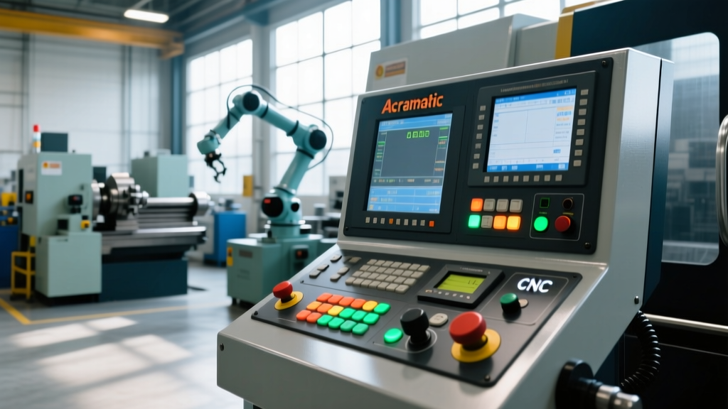
The Acramatic 2100 was the standard control for Cincinnati VMCs in the late 1990s and early 2000s. Unlike modern Fanuc or Haas interfaces, the Acramatic relies heavily on a proprietary soft-key menu structure that can confuse operators trained on newer systems. The most critical training module for this control is Manual Data Input (MDI) and Tool Offset management.
MDI and Tool Offset Best Practices
Operators frequently crash tools on Acramatic controls by misunderstanding the difference between Geometry and Wear offsets. The Acramatic 2100 does not automatically sum these values in the same visual hierarchy as a Fanuc 0i series.
- Access the Offset Page: Press the
OFFSEThard key, then select theGEOMsoft key. - Input Sequence: Type the tool number (e.g.,
T04), press theDOWN ARROWto move to the Z-axis field, type the measured Z-offset value, and pressINPUT. Never press INSERT, as this will shift the entire registry down and misalign all subsequent tools. - Wear Compensation: For fine-tuning part dimensions during a run, navigate to the
WEARsoft key. Add incremental values (e.g.,-0.0005) here. The control will algebraically sum Geometry and Wear, but operators must visually verify theACTIVEoffset page before cycling the start button.
Control Retrofit Economics: Acramatic vs. Modern Fanuc
Shop floor managers must eventually decide whether to train new hires on the legacy Acramatic interface or invest in a CNC control retrofit. The decision hinges on machine utilization rates and the availability of legacy control technicians.
| Metric | Keep Acramatic 2100 | Retrofit to Fanuc 0i-F Plus |
|---|---|---|
| Capital Cost | $0 (Sunk cost) | $28,000 - $42,000 |
| Machine Downtime | N/A | 3 to 5 Weeks |
| Operator Training Time | 40+ Hours (Steep learning curve) | 8 Hours (Industry standard) |
| Replacement Parts | Scarce; relies on eBay/salvage | Readily available via OEM |
| Memory / Program Storage | 512KB to 2MB (Requires DNC drip) | 2GB+ (USB / Network capable) |
For high-mix, low-volume job shops, the NIST Manufacturing Extension Partnership frequently recommends control retrofits to eliminate the bottleneck of DNC drip-feeding and reduce operator onboarding time. However, for dedicated production runs where the Acramatic is already proven, retaining the legacy control remains economically viable.
Integrating Modern DRO Systems on Manual Cincinnatis
The Cincinnati Series 2000 and 3000 manual knee mills are renowned for their heavy-duty spindle bearings and hardened box ways. To maintain tight tolerances (±0.0005") without relying on worn handwheel dials, shops integrate 3-axis DRO systems. While Heidenhain digital readouts like the ND 780 are the industry standard, the physical installation environment of a Cincinnati mill dictates the choice of linear scale technology.
Scale Selection by Axis
- X and Y Axes (Table and Saddle): Use sealed glass scales (e.g., Heidenhain LS 187). The Cincinnati table wipers are generally effective, and the scales can be mounted under the table overhang, protected from direct coolant splash and heavy chip loads.
- Z Axis (Knee or Quill): Never use glass scales on the Z-axis of a manual Cincinnati. The vibration from heavy face-milling operations and the constant exposure to way oil and coolant mist will destroy glass scale read-heads within months. Instead, install a magnetic or ball-type scale, such as the Newall Spherosyn or Sony Magnescale GB-ER. These tolerate oil immersion and heavy shock loads without signal loss.
Master Machinist Insight: "When mounting the Z-axis scale on a Series 2000, avoid the left-side column groove where way oil accumulates and chips pack in. Machine a custom 6061-T6 aluminum bracket to mount the Newall scale on the right-side dovetail, ensuring a minimum 0.005-inch air gap to prevent chip jamming between the read head and the scale tube."
Step-by-Step: Presetting a 3-Axis DRO on a Cincinnati Series 2000
Operators must follow a rigid sequence when establishing a workpiece zero on a DRO-equipped manual mill to account for backlash in the Cincinnati's older ball-screw or Acme thread assemblies.
- Eliminate Backlash: Always approach the final zero position by moving the table in the positive direction (moving left and forward). If you overshoot the mark, do not simply reverse the handwheel. You must move the table at least 0.100" in the negative direction, then re-approach in the positive direction to load the nut against the same side of the thread.
- Edge Finding: Use a mechanical edge finder (0.200" tip) spinning at 600 RPM. Break the edge, lock the axis, and subtract the 0.100" radius directly in the Heidenhain ND 780 interface by pressing
ABS/INCthenSETto 0.000. - Z-Axis Presetting: Use a dedicated Haimer 3D Sensor or a paper-feeler gauge (0.003" thick) on the spindle nose. If using a paper feeler, account for the paper thickness by inputting
Z = +0.003into the DRO after the paper tears, then re-zero the display. - Thermal Verification: Cincinnati castings absorb ambient shop heat. Re-check the Z-axis zero after 45 minutes of continuous milling, as the spindle housing will thermally expand, typically dropping the Z-axis zero by 0.0008" to 0.0015".
Troubleshooting Control & DRO Readout Errors
Operators must be trained to diagnose basic faults before calling a technician, reducing mean-time-to-repair (MTTR).
Acramatic Error 41: Following Error
Cause: The servo motor is drawing excessive current to keep up with the commanded position. On Cincinnati machines, this is rarely a bad drive; it is almost always mechanical binding.
Fix: Check the Bijur way lube unit reservoir. Verify the pressure switch is closing at 15-20 PSI. If lube is present, loosen the axis gib lock-nut and back off the gib adjusting screw by 1/8th of a turn to relieve way pressure.
DRO 'E' or 'Err' Flashing on Display
Cause: Signal loss between the linear scale and the readout head. Common on X/Y glass scales exposed to water-soluble coolants.
Fix: Power down the DRO. Remove the scale end-cap and clean the glass surface with isopropyl alcohol and a lint-free optical wipe. Never use shop rags or WD-40, which will leave a residue that scatters the LED light inside the read-head.
Operator Certification Checklist
Before an operator is cleared to run Cincinnati machine tools independently, shop floor supervisors must verify the following competencies:
- [ ] Demonstrated ability to clear an Acramatic 2100 E-stop alarm and safely restart the hydraulic power unit without dropping the tool magazine.
- [ ] Correct execution of MDI tool length offsets, distinguishing between Geometry and Wear registers.
- [ ] Proper backlash compensation technique when zeroing manual DRO axes on a Series 2000 mill.
- [ ] Identification of way-lube starvation symptoms (chatter marks on finish passes, high-pitch servo whine) before a catastrophic gib failure occurs.
- [ ] Safe extraction and cleaning of glass DRO scales without damaging the internal mylar wipers.