Prestige Machine and Tool DRO Maintenance Schedules
Optimize manual machining accuracy with our Prestige Machine and Tool DRO maintenance schedules, calibration protocols, and failure-mode troubleshooting.
The Critical Role of DRO Integrity in High-Precision Machining
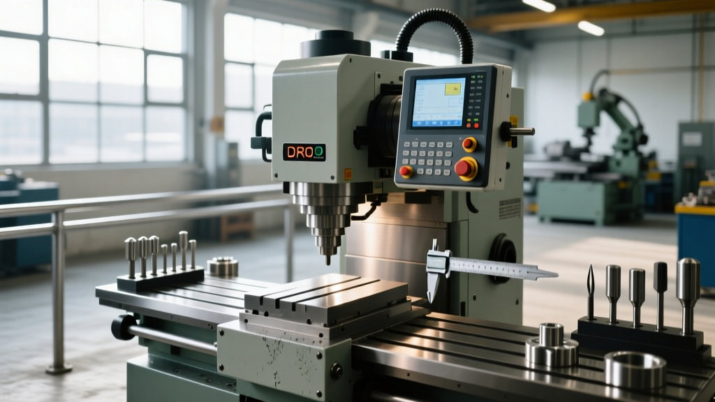
For facilities operating at the caliber of a Prestige Machine and Tool environment, the Digital Read Out (DRO) system is not merely a convenience; it is the primary dimensional feedback loop governing manual machining accuracy. While CNC machines rely on closed-loop servo encoders, manual mills and lathes equipped with DROs depend entirely on the physical integrity of linear scales and the processing stability of the display unit. A degraded DRO introduces cumulative pitch errors, cosine errors, and signal dropouts that directly compromise part tolerances.
Establishing a rigorous Prestige Machine and Tool DRO maintenance schedule transitions your shop from reactive scale replacements to predictive metrology management. This guide details exact service intervals, scale-specific diagnostic protocols, and calibration frameworks required to maintain sub-micron readout accuracy in harsh manufacturing environments.
⚠ CRITICAL WARNING: Solvent ContaminationNever use WD-40, acetone, or aggressive degreasers to clean optical glass scales or magnetic scale surfaces. These solvents degrade the polyurethane wiper lips and dissolve the optical coupling layers inside glass scales, causing permanent internal fogging. Use only 99% isopropyl alcohol or manufacturer-approved optical cleaners on a lint-free microfiber cloth.
Anatomy of DRO System Degradation
Before defining the maintenance schedule, it is essential to understand the specific failure modes that target DRO components. The harsh environment of a manual machine shop introduces three primary threats to readout accuracy:
- Coolant Ingress and IP Rating Failure: Most standard glass scales operate at IP53. If the wiper seals harden or the air purge system fails, alkaline coolants penetrate the scale housing, shorting the read head photodiodes or etching the glass grating.
- Mechanical Shock and Vibration: Heavy milling operations, particularly interrupted cuts or heavy facing on manual lathes, transmit high-frequency vibrations through the machine casting. Over time, this degrades the solder joints on the read head PCB and misaligns the scanning reticle.
- Cable Flex Fatigue: The umbilical cables connecting the scale to the display undergo thousands of articulation cycles. Internal wire strand breakage leads to intermittent signal loss, manifesting as 'jumping' digits on the display during axis movement.
Prestige Machine and Tool DRO Maintenance Schedules
To maintain NIST-traceable accuracy standards, maintenance must be segmented by frequency. The following matrix outlines the exact operational requirements for a high-utilization machine shop.
| Interval | Component Target | Action Protocol & Specifications |
|---|---|---|
| Daily | Scale Wipers & Air Purge | Visually inspect wiper lips for tearing. Verify air purge regulator is maintaining 0.5 to 1.0 bar (7-14 PSI) overpressure to prevent coolant mist ingress. |
| Weekly | Cable Carriers & Connectors | Check cable management arms for binding. Inspect scale-to-display connectors for bent pins or coolant residue. Clean pins with contact cleaner. |
| Monthly | Scale Surface & Read Head | Gently wipe exposed magnetic or inductive scale surfaces. For glass scales, check the external housing for micro-fractures or impact damage from dropped tooling. |
| Bi-Annual | Signal Diagnostics & Mounting | Run built-in DRO signal strength diagnostics. Check scale mounting bracket bolts with a torque wrench (typically 4-6 Nm) to ensure thermal expansion is not binding the scale. |
| Annual | Metrology Calibration | Perform full-axis laser interferometer verification or step-gauge calibration. Map pitch errors and update the DRO linear error compensation (LEC) parameters. |
Scale Technology & Specific Service Protocols
The maintenance approach must adapt to the specific linear encoder technology installed on the machine. According to Heidenhain Global Service guidelines, different encoder principles react differently to environmental contaminants.
1. Optical Glass Scales (e.g., Heidenhain LS Series)
Glass scales offer the highest resolution (down to 0.5 µm) but are the most fragile. They rely on a diffraction grating etched onto a glass substrate. The primary maintenance requirement is the air purge system. If your shop uses glass scales without a positive pressure air purge, you must retrofit a dedicated micro-regulator and coalescing filter to ensure the air supplied is completely oil-free and moisture-free. Moisture in the air lines will condense inside the scale housing, causing optical scattering and read errors.
2. Magnetic Scales (e.g., Newall MXB / Spherosyn)
Magnetic scales utilize a magnetized steel strip and a Hall-effect or magnetoresistive read head. As noted by Newall Electronics Support, these scales are inherently IP67 rated and immune to coolant ingress. However, their Achilles heel is ferrous swarf. Fine cast iron or steel dust can become magnetically bonded to the scale surface, altering the local magnetic flux density and causing micro-stutters in the readout. Monthly maintenance must involve wiping the scale with a specialized magnetic cleaning tool or a cloth dampened with light machine oil to lift ferrous particulates.
3. Inductive Scales (e.g., Sony Magnescale)
Inductive scales measure the change in mutual inductance between coils. They are highly resistant to shock, vibration, and oil mist. Maintenance is largely restricted to verifying the physical gap between the read head and the scale, which must be maintained within the manufacturer's strict tolerance (often 0.1 mm to 0.3 mm). Any physical impact that alters this air gap will result in immediate signal failure.
💡 PRO-TIP: Signal Verification via OscilloscopeFor advanced maintenance technicians, connecting an oscilloscope to the read head's sine/cosine output pins is the ultimate diagnostic tool. A healthy scale will produce perfect, circular Lissajous figures when the X and Y (sine and cosine) signals are plotted against each other. An elliptical pattern indicates signal amplitude mismatch (often due to dirty optics or scale degradation), while a figure-eight pattern indicates a phase shift error, usually caused by read head misalignment.
Annual Calibration & Error Compensation Framework
Maintaining the physical hardware is only half the battle; verifying the metrological accuracy is the second. The NIST Calibration Programs emphasize the necessity of traceable measurement standards in manufacturing. Annual calibration of a DRO system should follow this step-by-step framework:
- Thermal Stabilization: Allow the machine and the calibration environment to stabilize at 20°C (68°F) for a minimum of 4 hours. Thermal gradients in the machine casting will skew pitch error measurements.
- Laser Setup: Mount a laser interferometer (e.g., Renishaw XL-80 or API Radian) parallel to the axis of travel. Ensure the laser beam is aligned with the Abbe principle—meaning the beam path is as close to the cutting tool centerline as possible to minimize cosine and Abbe errors.
- Bidirectional Mapping: Program the laser software to take readings at 50 mm intervals across the full axis travel, moving in both the positive and negative directions. This captures backlash and hysteresis in the machine's physical lead screws or ways.
- LEC Parameter Entry: Most advanced DRO displays (like the Heidenhain ND 780 or Sony Magnescale DL330) feature a Linear Error Compensation (LEC) menu. Input the deviation data points generated by the laser software directly into the DRO. The DRO's processor will now mathematically correct the physical pitch errors of the machine in real-time.
Troubleshooting Matrix: Symptom to Resolution
When a DRO system exhibits anomalous behavior, use this diagnostic matrix to isolate the fault before ordering replacement parts.
| Symptom | Probable Root Cause | Corrective Action |
|---|---|---|
| Display jumps randomly by large increments (e.g., 10mm) without axis movement. | Electromagnetic Interference (EMI) or grounding loop. | Verify DRO display is grounded to the machine chassis. Ensure scale shield cables are terminated at the display end only, not both ends. |
| Axis reads correctly in one direction, but 'sticks' or drifts when reversing. | Scale contamination (oil/swarf) or failing read head LED. | Clean scale surface. Run signal strength diagnostic; if signal is below 60% of nominal, replace the read head unit. |
| DRO display completely blank or flashes error code 'E-04' / 'Signal Loss'. | Cable breakage internal to the umbilical or connector pin failure. | Perform continuity test on the scale cable with a multimeter. Replace cable assembly if any of the 9-pin D-sub connections show infinite resistance. |
| Measured distance does not match physical travel (scaling error). | Incorrect resolution setting in DRO parameters or thermal expansion. | Verify the DRO parameter matches the scale's exact grating period (e.g., 5 µm vs 1 µm). Recalibrate using a certified step gauge. |
The ROI of Preventive DRO Maintenance
The financial argument for strict adherence to a Prestige Machine and Tool DRO maintenance schedule is undeniable. A reactive approach—waiting for a scale to fail due to coolant ingress—results in immediate machine downtime. Replacing a high-resolution 1000mm glass scale costs between $1,800 and $2,800, plus $1,200 to $2,000 for the read head, alongside 4 to 6 hours of skilled technician labor for installation and recalibration. Conversely, a preventive maintenance program requiring $150 annually in replacement air filters, wiper seals, and isopropyl alcohol preserves the asset, ensures NIST-traceable part accuracy, and eliminates catastrophic metrology failures on the shop floor.