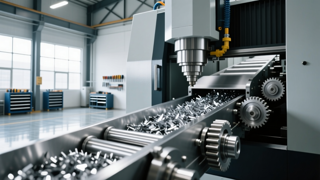
Advanced Machine Tool Tech: Chip Conveyor & Swarf Specs
Explore the technical specifications and mechanics of modern machine tool tech for chip conveyors and swarf management, including costs and failure modes.
High-speed CNC turning centers and 5-axis milling machines routinely generate upwards of 150 lbs of swarf per hour. When evaluating modern machine tool tech, swarf management is frequently treated as an afterthought, yet improper chip evacuation directly causes up to 18% of unplanned spindle downtime. The physics of chip volume expansion dictate that one cubic inch of solid metal yields three to five cubic inches of loose chips. If the conveyor system cannot match the material removal rate (MRR), chips accumulate in the work envelope, leading to recutting, tool breakage, and severe coolant starvation.
CRITICAL WARNING: Never pair a standard hinge-belt conveyor with fine, powdery cast iron or aluminum swarf. Fine chips will bypass the belt hinges, infiltrate the sprocket mechanism, and cause catastrophic motor burnout within 40-60 operating hours.The Mechanics of Swarf Evacuation
At its core, a chip conveyor is a material handling system engineered to overcome the specific morphology of metal chips while submerged in or coated with cutting fluid. The drive motor, typically a 0.5 HP to 2.0 HP three-phase AC motor coupled with a cycloidal gearbox, provides the high torque and low speed required to pull heavy, interlocked chip masses up an inclined throat (usually pitched between 35° and 60°). Modern systems utilize variable frequency drives (VFDs) and programmable logic controllers (PLCs) to implement auto-reverse logic. When the motor amperage spikes—indicating a jam—the PLC reverses the belt for 3 to 5 seconds to dislodge the obstruction before resuming forward motion.
Core Machine Tool Tech: Conveyor Specifications Matrix
Selecting the correct conveyor architecture requires matching the system's mechanical limits to the shop's specific machining processes. Below is a technical comparison of the four primary conveyor types utilized in modern manufacturing facilities.
| Conveyor Type | Ideal Swarf Morphology | Operating Speed | Filtration Capability | 2026 Cost Range (USD) |
|---|---|---|---|---|
| Hinge Belt | Brittle, C-shaped, heavy chunks | 15 - 30 ft/min | None (Gross removal only) | $2,500 - $5,500 |
| Scraper / Track-Belt | Stringy, ductile, sticky (Aluminum) | 5 - 15 ft/min | None | $4,000 - $8,000 |
| Auger / Screw | Fine, powdery, granular (Cast Iron) | 10 - 25 RPM | None | $1,500 - $3,500 |
| Vacuum / Drum Filter | All types (focus on coolant clarity) | Continuous (up to 150 GPM) | 10 - 25 Micron | $15,000 - $45,000+ |
Matching Swarf Morphology to Material Grades
The geometry of the chip produced is dictated by the material's shear strength and the tooling geometry. Machine tool tech must be adapted to handle these distinct physical profiles.
6061-T6 Aluminum (Stringy and Ductile)
Aluminum machining produces long, stringy chips that easily tangle into massive 'bird-nests.' Standard hinge belts fail here because the stringy chips slide over the smooth metal slats without being carried upward. For 6061-T6 and similar alloys, specify a scraper conveyor or a hinge belt equipped with 1.5-inch raised cleats and a textured top surface. Systems like the Mayfran Track-Belt utilize a continuous rubberized track that physically grabs and pulls ductile swarf up the incline without slipping.
4140 Pre-Hardened Steel (Brittle and Abrasive)
Steel turning operations typically yield brittle, C-shaped or 6-shaped chips. These are highly abrasive and heavy. A heavy-duty steel hinge belt (minimum 14-gauge carbon steel slats) is the industry standard. The primary technical requirement here is impact resistance; the conveyor bed must feature UHMW (Ultra-High Molecular Weight) polyethylene wear strips to absorb the kinetic energy of heavy steel chips dropping from the chuck, preventing premature bed deformation.
Titanium Ti-6Al-4V (High Heat and Work Hardening)
Titanium generates short, sharp chips that retain immense amounts of heat. If allowed to accumulate in the machine sump, these hot chips will rapidly degrade water-soluble coolants, causing bacterial growth and pH drops. Furthermore, titanium chips can work-harden and weld themselves to the conveyor bed. Specify conveyors with integrated coolant chillers and highly polished stainless-steel (304 or 316 grade) troughs to prevent chip adhesion.
PRO TIP: When running high-pressure coolant (HPC) systems at 1,000+ PSI through the spindle, the sheer volume of fluid returning to the sump can overwhelm standard conveyors. Ensure your conveyor's coolant return flange is rated for a minimum of 1.5x the maximum GPM output of your HPC pump to prevent sump overflow.Advanced Filtration and Coolant Management
Gross chip removal is only half the battle. Modern precision machining requires ultra-clean coolant to protect high-pressure spindle bearings and prevent micro-scratches on finished surfaces. This is where advanced filtration machine tool tech becomes mandatory.
Vacuum drum filters, such as those engineered by Hennig, utilize a continuous paper or synthetic filter media wrapped around a rotating drum. A vacuum pump pulls coolant through the media, trapping particles down to 10 microns. When the cake of fine swarf builds up and restricts flow, a differential pressure switch triggers the drum to rotate, advancing fresh media and dropping the saturated swarf into a secondary discharge chute. While the capital expenditure for a vacuum filtration system ranges from $15,000 to over $45,000, the ROI is typically realized within 14 months through extended coolant life (reducing fluid disposal costs by up to 60%) and decreased tool wear.
Troubleshooting Decision Tree: Conveyor Failure Modes
Even the most robust conveyor systems will fail if operating parameters drift outside their design specifications. Use this diagnostic framework to address common mechanical and electrical faults.
- Symptom: Drive motor thermal overload trips repeatedly.
Root Cause: 'Bird-nesting' in the conveyor throat or severe chain tension loss causing the belt to bind against the housing.
Corrective Action: Install a mechanical shear-pin torque limiter on the drive shaft to protect the gearbox. Update the PLC logic to include a 'reverse-pulse' routine that runs the motor backward for 2 seconds every 45 minutes to clear minor throat obstructions before they lock the drive. - Symptom: Coolant starvation at the machine pump; sump level dropping rapidly.
Root Cause: Fine swarf is bypassing the conveyor hinges and accumulating in the machine's internal sump, clogging the pump intake strainer.
Corrective Action: Retrofit the existing hinge belt with overlapping side-seal wipers. If machining cast iron or fine-grain aluminum, replace the primary conveyor with a dual-stage system (auger for bulk removal + vacuum filter for fine particulate). - Symptom: Conveyor belt tracking to one side, causing edge wear and jamming.
Root Cause: Uneven chip loading across the belt width or worn sprocket teeth allowing lateral drift.
Corrective Action: Install V-guided tracking strips on the underside of the belt and matching grooves in the sprockets. Ensure the chip chute from the machine is centered to distribute the swarf load evenly across the conveyor width.
Integrating the correct chip conveyor and swarf management system is not merely a housekeeping task; it is a critical component of the overall machining ecosystem. By aligning conveyor specifications—speed, torque, filtration micron ratings, and materials—with the exact morphology of the swarf being produced, shops can eliminate recutting, stabilize coolant chemistry, and maximize spindle utilization.