Beyond the Machine Tools APUSH Definition: Safety Interlock Maintenance
Move past the historical machine tools APUSH definition to master CNC safety interlock maintenance schedules, E-stop testing, and OSHA compliance.
From the Machine Tools APUSH Definition to Modern CNC Safety Realities
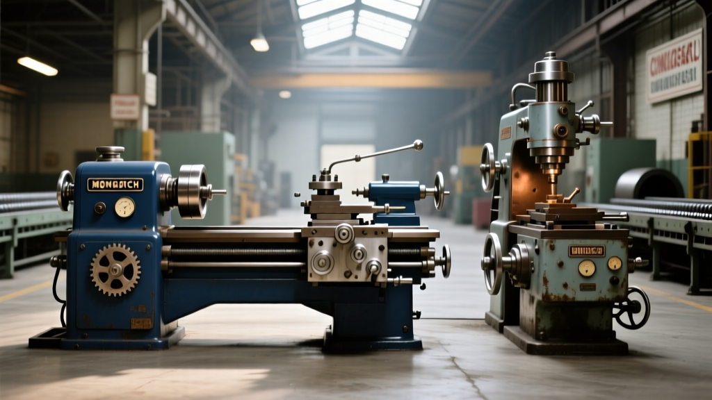
When high school students encounter the machine tools APUSH definition in Advanced Placement U.S. History, they are typically studying the 19th-century American System of Manufacturing. They learn about Simeon North and Eli Whitney utilizing early milling machines to produce interchangeable musket parts. While this historical context is vital for understanding industrialization, it offers zero preparation for the lethal kinetic energy managed by a modern 5-axis CNC machining center.
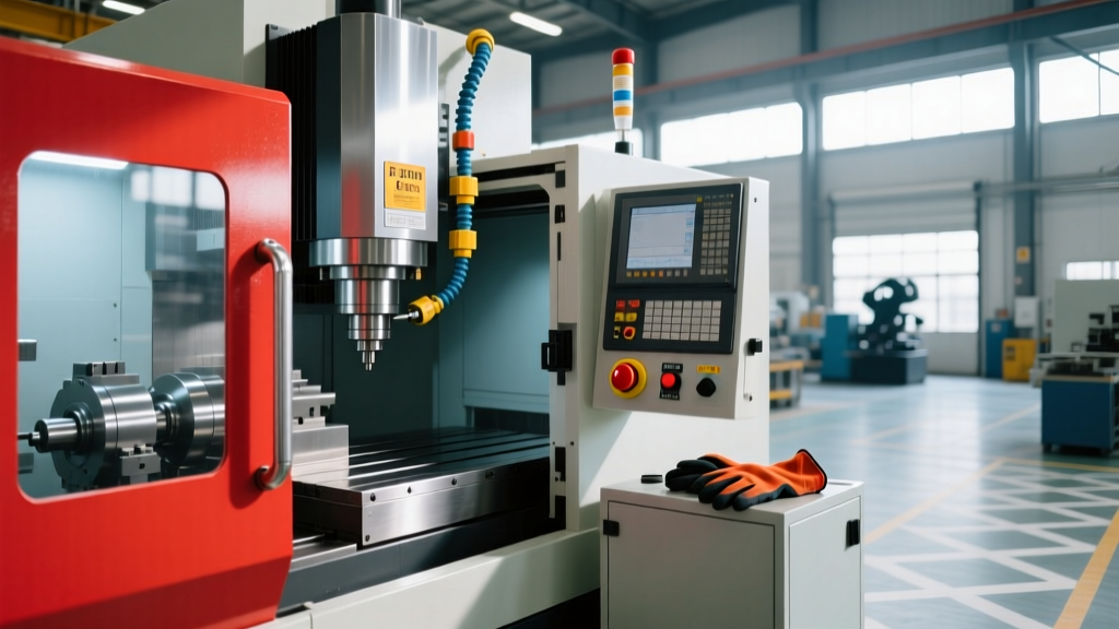
Today, a machine shop does not rely on leather belts and steam engines. A 2026 Mazak INTEGREX i-500 or Haas UMC-750SS operates with 12,000 RPM spindles, 1,000 psi coolant through-spindle systems, and rapid traverse rates exceeding 1,000 inches per minute. The historical definition has evolved into a complex ecosystem of programmable logic controllers (PLCs), dual-channel safety relays, and RFID-coded door interlocks. Maintaining these safety systems is not optional; it is a rigorous, legally mandated discipline governed by OSHA machine guarding standards and ISO 13849-1 performance levels.
The Anatomy of Modern Safety Interlock Systems
Before establishing a maintenance schedule, maintenance managers must understand the hardware protecting their operators. Modern CNC safety circuits are generally divided into three primary subsystems:
- Emergency Stop (E-Stop) Circuits: Hardwired, dual-channel (Category 4 / PL e) circuits utilizing safety relays like the Pilz PNOZ X3 or Allen-Bradley Guardmaster 440R. These physically cut power to the spindle drive and axis servo amplifiers.
- Door Interlocks: Transitioning away from mechanical tongue-and-groove switches, modern machines use RFID-coded non-contact switches (e.g., Euchner CTP or Schmersal AZM400). These prevent operators from defeating the switch with a simple zip-tie or piece of tape.
- Light Curtains and Area Scanners: Optoelectronic devices like the SICK microScan3 that create invisible infrared barriers around the machine envelope, triggering an E-stop if breached during automatic operation.
Mandatory Maintenance Schedules for Safety Interlocks
Safety interlocks are not 'set and forget' components. Vibration, way oil, conductive metallic swarf, and thermal cycling degrade these systems over time. Implement the following tiered maintenance schedule to ensure continuous compliance and operator safety.
Daily Operator Verification (Shift Start)
Operators are the first line of defense. Before the first cycle is run, the following checks must be logged on the machine's daily TPM (Total Productive Maintenance) sheet:
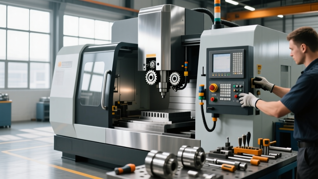
- E-Stop Push Test: Depress every E-stop button on the machine pendant and operator console. Verify that the spindle stops within 1.5 seconds and that the control displays the correct E-stop alarm (e.g., FANUC Alarm EX1001 or Haas Alarm 105).
- Door Interlock Cycle Test: Close the main enclosure door. Attempt to start the spindle in MDI mode. Open the door slightly; the spindle must immediately coast to a stop, and the coolant pump must shut off.
- Visual Inspection: Check light curtain lenses for coolant mist buildup and wipe clean with a microfiber cloth and isopropyl alcohol.
Monthly Preventative Maintenance (PM)
Machine technicians must perform physical measurements and electrical validations during the monthly PM window.
- RFID Actuator Alignment Check: Non-contact RFID switches have strict sensing tolerances. For a Euchner CTP switch, the assured operating distance is typically 5mm to 15mm. Use a feeler gauge to verify the gap between the sensor and the actuator. If machine vibration has shifted the door hinge and the gap exceeds 18mm, the switch will intermittently fault, causing random 'Door Open' alarms mid-cycle.
- E-Stop Button Mechanical Inspection: Pull and twist the E-stop mushroom heads to ensure the internal mechanical latch releases smoothly. Inspect the rubber bellows for micro-tears where coolant could ingress and short the NC (Normally Closed) contact blocks.
- Light Curtain Alignment Verification: Use the manufacturer's alignment tool or check the diagnostic LED bar on the receiver unit. A misalignment of just 2 degrees over a 6-foot span can cause the safety beam to drop, resulting in nuisance tripping.
Annual Electrical Validation
Once a year, a licensed electrician or certified controls technician must validate the integrity of the safety circuit wiring.
- Contact Resistance Testing: Inject a low current through the E-stop circuit loop and measure the voltage drop. Total loop resistance should remain under 150 milliohms. A reading above 500 milliohms indicates oxidation on the safety relay terminals or internal degradation of the E-stop contact blocks.
- Relay Drop-Out Time Measurement: Using an oscilloscope or a specialized safety relay tester, measure the time from the E-stop button actuation to the physical opening of the main contactor. This must strictly align with the machine builder's original CE/UL certification documentation (usually < 20 milliseconds for the relay, plus the mechanical braking time of the drive).
Troubleshooting Common Interlock Failure Modes
When safety systems fail, they usually fail 'safe' (preventing the machine from running). However, diagnosing the root cause quickly is essential to minimizing downtime. Below is a diagnostic matrix for common interlock faults on modern CNC equipment.
| Symptom / Alarm | Root Cause | Corrective Action | Estimated Cost / Time |
|---|---|---|---|
| Door closed, but control displays 'Door Open' (e.g., Haas Alarm 105) | Mechanical tongue switch worn, or RFID actuator magnetized with ferrous swarf, blocking the signal. | Clean actuator with isopropyl. If pitted or mechanically bound, replace the switch assembly. | $180 - $350 (Part) 30 mins labor |
| E-stop button will not pull out / reset | Internal contact block binding due to synthetic coolant ingress crystallizing inside the housing. | Replace the entire E-stop head and NC contact blocks (e.g., Allen-Bradley 800FP series). Do not attempt to clean internal contacts. | $85 (Part) 15 mins labor |
| Safety Relay (Pilz PNOZ) CH1/CH2 Fault LED illuminated | Wiring discrepancy or one channel's contactor auxiliary feedback is failing to close within the 3-second synchronization window. | Trace the dual-channel wiring. Check the auxiliary NO contacts on the main spindle contactor for carbon pitting. | $45 (Contactor aux block) 2 hours diagnostics |
| Light curtain nuisance tripping during rapid axis moves | Vibration from heavy cutting or rapid deceleration is shaking the emitter/receiver brackets out of optical alignment. | Reinforce mounting brackets with gussets. Re-align using the laser alignment tool and apply Loctite 243 to mounting bolts. | $20 (Hardware) 1 hour labor |
Upgrading Legacy Systems to ISO 13849-1 Standards
Many job shops operating older equipment (manufactured prior to 2015) rely on Category 1 or Category 2 safety architectures. These legacy systems use single-channel wiring or simple PLC logic to monitor E-stops, which presents a massive liability. If a single wire shorts to ground, the E-stop button becomes completely ineffective.
Upgrading these legacy machines to ISO 13849-1 Category 3 or 4 (Performance Level d or e) is a critical capital maintenance project. This involves:
- Removing the E-stop hardwiring from the standard machine PLC inputs.
- Installing a dedicated, certified safety relay module (e.g., Pilz PNOZsigma series) in the electrical cabinet.
- Rewiring all E-stop buttons in a dual-channel loop, ensuring that the physical wires for Channel 1 and Channel 2 are routed in separate conduit paths to prevent a single pinch-point from severing both channels.
- Integrating the safety relay's output into the CNC drive's Safe Torque Off (STO) terminal, which electronically disables the servo drives without relying solely on mechanical contactors.
"A safety interlock is only as reliable as its last validation test. In a high-production environment, treating safety circuit maintenance as a secondary task guarantees an eventual catastrophic failure. Documenting every monthly relay drop-out test is your only shield during an OSHA post-incident audit."
Documenting Interlock Service for Compliance
Performing the maintenance is only half the battle; proving it was done is what protects the business. The OSHA 1910.212 general requirements for all machines dictate that guarding and safety devices must be maintained in proper working order.
Implement a digital CMMS (Computerized Maintenance Management System) workflow for safety interlocks:
- Photographic Evidence: Require technicians to upload a photo of the multimeter reading during the annual contact resistance test to the work order.
- Component Serialization: Track the installation date and batch number of safety relays and contactors. Safety relays have a finite mechanical lifecycle (often rated for 100,000 switching cycles). If a machine cycles its E-stop 50 times a day, the relay must be proactively replaced every 5.5 years, regardless of whether it currently passes testing.
- Operator Sign-Off: Ensure the daily TPM checklist requires a physical or digital signature verifying the morning E-stop push test, shifting the safety culture from a passive reliance on engineering to active daily participation.
The evolution from the rudimentary milling machines found in the machine tools APUSH definition to today's multi-axis, high-velocity CNC centers represents a triumph of engineering. However, that kinetic potential demands equal respect. By adhering to strict, data-driven maintenance schedules for safety interlocks and E-stop circuits, manufacturing facilities ensure that their most valuable assets—their operators—return home safely at the end of every shift.