L&L Machine Tool Safety Interlocks: Operator Training & E-Stop Guide
Master L&L Machine Tool safety interlocks and E-stop protocols. This operator guide covers ISO 13849-1 standards, reset procedures, and fault diagnosis.
The Critical Role of Interlocks in Modern Machining
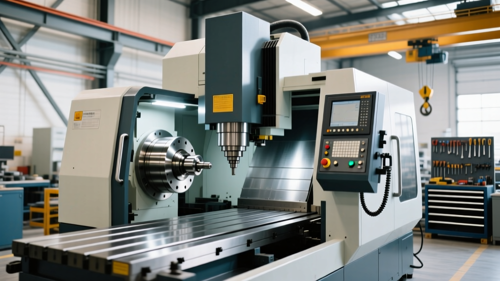
Operating heavy-duty CNC lathes, multi-axis machining centers, and manual mills requires strict adherence to safety protocols. For facilities running equipment supported by L&L Machine Tool networks, understanding the specific safety interlock logic and emergency stop (E-stop) architectures is not just a regulatory requirement—it is the primary barrier between routine production and catastrophic injury. According to recent occupational safety data, machinery-related amputations and crushing injuries consistently rank among the most severe workplace incidents, with average direct medical and compensation costs exceeding $120,000 per incident, excluding OSHA fines and downtime.
This guide provides advanced operator training on the safety interlocks and E-stop systems found on modern machine tools. We will bypass generic safety platitudes and focus on the exact hardware architectures, ISO performance levels, and daily verification procedures required to maintain a safe, compliant, and highly productive shop floor.
The Anatomy of Compliance: ISO 13849-1 and OSHA 1910.212
Modern machine tool safety systems are governed by strict international and federal standards. In the United States, OSHA 1910.212 outlines the general requirements for all machines, mandating that one or more methods of machine guarding shall be provided to protect the operator and other employees in the machine area from hazards such as those created by point of operation, ingoing nip points, rotating parts, flying chips, and sparks.
On a technical level, L&L Machine Tool equipment utilizes control systems designed to meet ISO 13849-1:2015 Safety of machinery standards. This standard categorizes safety circuits by Performance Level (PL). For heavy CNC equipment with high kinetic energy (such as a 15,000 RPM spindle or a rapid-traverse 40-taper tool changer), the safety interlocks must typically achieve a Performance Level 'd' (PLd) or 'e' (PLe), utilizing Category 3 or Category 4 redundant architectures.
Operator Insight: A Category 3 architecture means that a single fault in the safety circuit will not lead to the loss of the safety function. If one door switch relay fails, the redundant channel will still trigger the E-stop, and the machine's PLC will flag a 'Safety Circuit Fault' on the HMI, preventing the machine from cycling until maintenance resolves the hardware discrepancy.Interlock Hardware: Magnetic vs. RFID vs. Mechanical Tongue
Operators must understand the physical hardware securing the machine enclosure. Defeating or improperly maintaining these switches is a leading cause of OSHA machine guarding citations. Modern enclosures utilize three primary types of interlock switches, each with distinct failure modes that operators must monitor during daily inspections.
| Switch Type | Operating Principle | Common Failure Modes & Operator Checks |
|---|---|---|
| RFID Coded Non-Contact | Uses encrypted radio frequency to verify the unique actuator. Immune to magnetic fields. | Failure: Coolant buildup blocking the RF window. Check: Wipe sensor face with isopropyl alcohol; ensure LED indicator shows solid green when closed. |
| Mechanical Tongue | A physical steel tongue inserts into the switch housing, mechanically blocking the release mechanism. | Failure: Door sag misaligns the tongue, causing binding or shearing. Check: Verify door hinges for play; ensure tongue enters the slot without scraping the housing edges. |
| Magnetic Non-Contact | Relies on magnetic fields to close internal reed switches. Lower security than RFID. | Failure: Ferrous swarf (chips) clinging to the magnet, tricking the sensor. Check: Inspect for metal shavings accumulation; clean daily in cast iron machining operations. |
Emergency Stop (E-Stop) Logic: Category 0 vs. Category 1
Pressing the red mushroom button is a universal reaction to danger, but operators must understand what happens inside the machine's drive system when an E-stop is actuated. Under ISO 13850, E-stop functions are categorized by how the machine removes power from hazardous actuators.
Category 0 Stop: Coast to Zero (Immediate Power Removal)
In a Category 0 stop, the main contactor drops out immediately, removing electrical power from the spindle drive and servo amplifiers. The spindle coasts to a halt via natural friction. On a high-mass CNC lathe chuck spinning at 3,000 RPM, a coast-to-zero stop can take over 45 seconds. Operators must never open the primary enclosure door immediately after hitting a Category 0 E-stop, as the kinetic energy remains lethal.
Category 1 Stop: Controlled Deceleration
A Category 1 stop commands the spindle drive to utilize dynamic braking resistors to aggressively decelerate the spindle to a complete halt, and then removes power. This is the standard for most modern CNC machining centers. The drive monitors the RPM; once it reaches 0 RPM, the safety contactors open. Operators should listen for the distinct 'clack' of the main contactors disengaging only after the spindle whine has completely ceased.
CRITICAL WARNING: Never use the E-stop button as a standard 'Cycle Stop' or 'Pause' button. Repeatedly triggering the E-stop during normal operation forces the machine's main contactors to drop out under load, causing severe electrical arcing. Over time, this will weld the contactor contacts shut, rendering the E-stop completely useless in a genuine emergency.Shift-Start Verification Protocol
Relying on the assumption that safety circuits are functional is a critical operational error. Operators must perform a physical verification of the L&L Machine Tool safety interlocks at the start of every shift. This 3-minute protocol prevents catastrophic failures later in the production run.
- The Door Actuation Test: With the spindle running at a low RPM (e.g., 200 RPM) in MDI mode, safely open the primary enclosure door. Verify that the spindle immediately initiates its braking sequence and the feed axes halt. If the spindle continues to spin, lock out the machine and notify maintenance immediately.
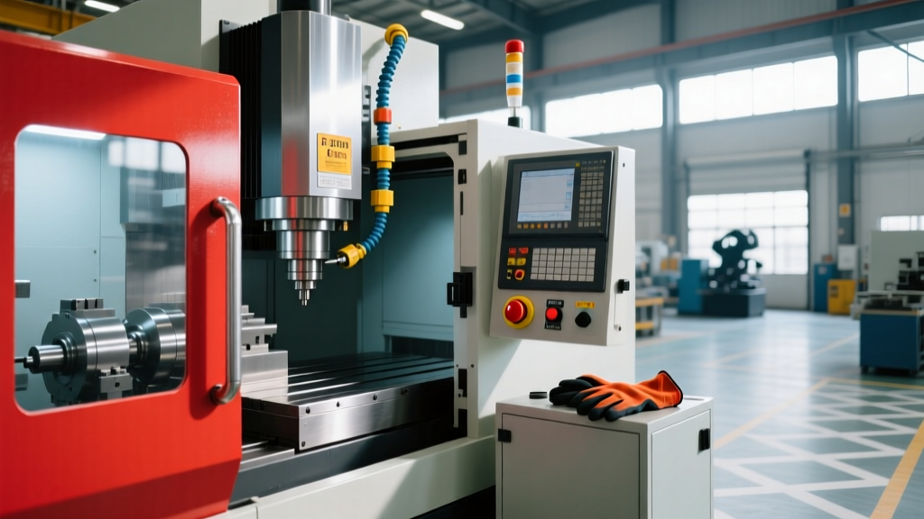
- The E-Stop Voltage Drop Test: Press the E-stop button on the main operator pendant. Attempt to start the hydraulic pump or coolant motor via the HMI. The PLC must reject the command and display a 'Safety Circuit Open' alarm.
- Reset Sequence Verification: Twist and pull the E-stop button to release it. Press the physical 'Reset' button on the electrical cabinet (not just the HMI soft key). Verify that the main contactor engages with a solid, singular 'thud' rather than a rapid chattering sound, which indicates low control voltage or a failing contactor coil.
Troubleshooting Nuisance Trips and Coolant Ingress
One of the most dangerous situations in a machine shop is 'alarm fatigue'—when operators become desensitized to frequent safety interlock trips and begin looking for ways to bypass them. Understanding the root causes of nuisance trips allows operators to address the actual mechanical issue rather than resorting to dangerous workarounds.
Vibration-Induced Actuator Misalignment
Heavy roughing operations, such as interrupted cuts on forged steel, generate massive harmonic vibrations. Over time, these vibrations can loosen the mounting bolts on the door actuator tongue. If the tongue shifts even 2 millimeters, it may scrape the side of the interlock switch housing during door closure, failing to depress the internal safety plungers. Solution: Operators should inspect the wear pattern on the mechanical tongue. If the polished wear mark is off-center or the tongue shows galling, the actuator bracket requires realignment and Loctite application on the mounting hardware.
IP69K Washdown Failures
In environments utilizing high-pressure coolant systems or aggressive washdown procedures, standard IP67-rated interlock switches will eventually fail. High-pressure alkaline cleaning agents can breach the switch seals, causing internal corrosion that leads to intermittent open-circuit faults. If your machine experiences random 'Door Open' alarms during heavy coolant splash cycles, the switch requires upgrading to an IP69K-rated stainless steel housing designed to withstand high-pressure, high-temperature washdowns.
The True Cost of Bypassing Safety Circuits
Tape, zip-ties, and spare magnets used to defeat interlocks are the fastest route to severe OSHA penalties and life-altering injuries. Under current 2026 enforcement guidelines, OSHA classifies the deliberate bypassing of machine guarding as a 'Willful Violation.' Willful violations carry a minimum penalty of over $16,000 per instance, with maximum fines exceeding $161,000 per violation. More importantly, if an operator is injured on a machine where the interlock was intentionally defeated, the facility faces severe criminal liability and civil litigation.
Operators must treat every safety interlock and E-stop circuit on L&L Machine Tool equipment as an active, life-saving component. When a fault occurs, the correct protocol is to diagnose the hardware failure, replace the compromised switch with an OEM-equivalent rated for the correct ISO Performance Level, and verify the circuit logic before resuming production.