Machine Cutting Tools Safety: Interlocks & E-Stops Guide
Master safety interlocks and E-stop protocols for machine cutting tools. Includes daily testing routines, fault troubleshooting, and NFPA 79 specs.
The Critical Intersection of Operators and Machine Cutting Tools
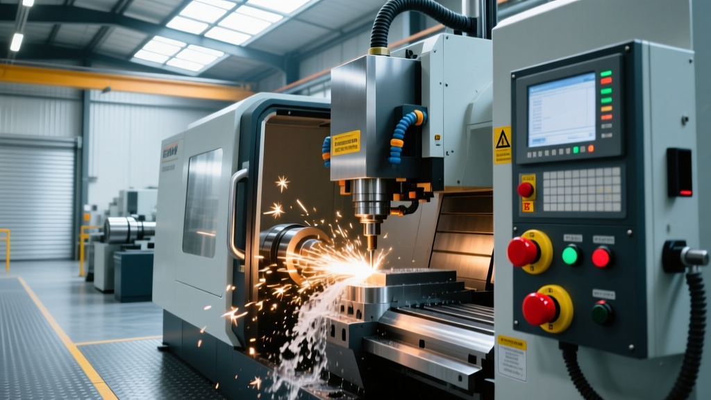
When operators load raw stock into a CNC mill or adjust workholding on a lathe, the proximity to high-speed machine cutting tools demands absolute certainty in safety systems. A 12,000 RPM spindle or a rapid-traversing carriage leaves zero margin for human error. While personal protective equipment (PPE) and operator training are vital, the primary defense against catastrophic injury lies in engineered safety controls: specifically, safety interlocks and emergency stop (E-stop) circuits.
Modern manufacturing environments in 2026 rely heavily on smart, networked safety components. However, the fundamental principles of machine guarding remain governed by strict OSHA regulations and international standards. According to OSHA Standard 1910.212 (General Requirements for All Machines), machines with rotating parts, flying chips, and hazardous cutting zones must be equipped with reliable guarding mechanisms that prevent operator exposure during the machining cycle. This guide details the technical specifications, daily verification protocols, and troubleshooting frameworks required to maintain these life-saving systems.
⚠️ CRITICAL SAFETY WARNING: Emergency stop buttons are strictly for emergency conditions. Using an E-stop as a standard "cycle stop" or "off" switch causes premature wear on contactors and bypasses the machine's controlled deceleration routines, leading to mechanical shock and potential spindle bearing damage.Decoding E-Stop Categories: NFPA 79 and ISO 13850
Not all red buttons function identically. Under NFPA 79 (Electrical Standard for Industrial Machinery) and ISO 13850, E-stop functions are classified into distinct categories based on how they remove power from the machine cutting tools and drive systems.
Category 0: Immediate Power Removal
A Category 0 stop functions by immediately removing electrical power to the machine actuators. This is an uncontrolled stop. When triggered, the spindle drive and servo amplifiers lose power instantly. The machine cutting tools will coast to a halt based on their rotational inertia. This is mandatory for machines where immediate electrical isolation is the only way to prevent severe hazards, such as electrical fires or uncontrolled axis runaway.
Category 1: Controlled Stop with Power Removal
A Category 1 stop initiates a controlled deceleration of the machine axes and spindle using dynamic braking or regenerative drives, and then removes power once the machine reaches a standstill. This is the preferred method for heavy-duty CNC lathes and large gantry mills, as it prevents the mechanical shock and tooling damage associated with abrupt power loss, while still ensuring the machine cutting tools reach zero RPM safely.
"An E-stop circuit must utilize hardwired, positively guided safety relays or fail-safe solid-state logic. Standard PLC outputs are never permissible for direct E-stop actuation due to the risk of software faults or processor lockups."
Safety Interlock Technologies for Machine Guarding
Interlocks ensure that machine cutting tools cannot be energized if the operator access door is open, and conversely, that the door cannot be opened while the tools are in motion. The evolution from mechanical switches to RFID-based sensors has drastically reduced false faults and defeated guards.
| Interlock Type | Mechanism & Examples | Vulnerability to Defeat | Best Application |
|---|---|---|---|
| Mechanical Tongue | Physical key inserts into switch (e.g., Schmersal AZ 15/16). Relies on physical actuation. | High. Operators can tape down the actuator or use a spare "cheat key" to bypass. | Low-risk enclosures, manual milling machines, non-hazardous coolant splash guards. |
| Trapped Key | Sequential key transfer system (e.g., Castell). Key must be turned to isolate power before it can be removed to unlock the door. | Very Low. Requires physical destruction of the lock mechanism to bypass. | High-voltage cabinets, large automated machining cells, laser cutting enclosures. |
| RFID Non-Contact | Coded magnetic/RFID actuator (e.g., Euchner NZ.VS, Pilz PSENmech). Reads unique digital signature. | Extremely Low. Cannot be defeated by standard magnets or duplicate physical keys. | CNC machining centers, environments with heavy coolant/chip contamination where mechanical switches fail. |
The Danger of Guard Defeat
According to the OSHA Machine Guarding guidelines, bypassing or defeating safety interlocks is a leading cause of amputations and fatalities in machine shops. Modern RFID interlocks with IO-Link communication now alert facility managers via the machine's HMI if an actuator is removed from the door, effectively eliminating the "tape over the sensor" cheat method prevalent in older mechanical systems.
Daily Operator Verification Protocols
Safety systems are only effective if verified. Shop floor managers must enforce a strict daily testing routine at the beginning of every shift before any machine cutting tools are put into production. This 5-step protocol takes less than three minutes but guarantees circuit integrity.
- Visual Inspection: Check the physical condition of the E-stop mushroom heads. Ensure they are not cracked, packed with metal swarf, or jammed in the depressed position. Verify that interlock actuators are tightly fastened to the guard doors with no visible play.
- E-Stop Functional Test: With the machine powered on and the spindle idling (no cutting load), depress the primary operator panel E-stop. Verify the spindle halts immediately (or within the controlled Category 1 timeframe) and the control screen displays the specific E-stop fault code.
- Reset Verification: Twist to release the E-stop. Attempt to clear the alarm. The machine should not restart automatically; it must require a deliberate secondary action (e.g., pressing a physical "Cycle Start" or "Reset" button) to resume operation.
- Interlock Cycle Test: Close the main operator door. Verify the "Door Closed" indicator illuminates. Open the door while the machine is in a rapid traverse state (using a safe, pre-programmed dry-run macro). The machine axes must instantly halt feed motion.
- Guard Locking Check (if applicable): For machines with solenoid guard locking (preventing door opening until the spindle reaches 0 RPM), attempt to pull the door handle immediately after initiating a spindle stop. The door must remain mechanically locked until the HMI confirms zero rotational energy.
Troubleshooting Interlock and E-Stop Faults
When safety circuits fail, production stops. Diagnosing these faults requires understanding both the electrical logic and the physical environment of the machine shop. Below is a diagnostic matrix for common failures encountered with machine cutting tools and their associated safety hardware.
| Symptom / Fault Code | Root Cause Analysis | Corrective Action |
|---|---|---|
| Safety Relay Trips Intermittently during heavy roughing cycles. | High-frequency vibration from aggressive machine cutting tools is causing micro-disconnects in mechanical limit switches or loose wiring in the E-stop daisy chain. | Upgrade to solid-state RFID interlocks (e.g., Schmersal AZM40) which tolerate up to ±3mm of misalignment and vibration. Torque all terminal block screws to manufacturer specs. |
| Door Interlock Fails to Engage despite door appearing fully closed. | Chip accumulation or dried coolant on the RFID sensor face, or door hinges have sagged, pushing the actuator outside the 5mm hysteresis threshold. | Clean sensor face with isopropyl alcohol (never use harsh solvents that craze the PBT plastic). Realign door hinges and shim the actuator block to restore optimal air gap. |
| E-Stop Depressed, but Spindle Coasts for an extended duration (>10 seconds). | VFD dynamic braking resistor has failed open-circuit, or the safety relay is incorrectly wired to bypass the drive's enable signal, relying solely on coasting. | Test braking resistor for continuity. Verify wiring schematic against NFPA 79 Category 1 requirements to ensure the drive's "Safe Torque Off" (STO) inputs are being triggered. |
| Guard Lock Solenoid Buzzes but door remains locked after spindle stops. | Coolant ingress into the solenoid coil causing internal corrosion, or mechanical binding due to misaligned door latch applying lateral shear force to the locking pin. | Replace the solenoid module with an IP67-rated sealed unit. Adjust the door strike plate to ensure the locking pin slides in axially without side-loading. |
Advanced Integration: Safe Torque Off (STO) in Modern Drives
In 2026, the standard for protecting operators from machine cutting tools driven by servo motors and VFDs is the Safe Torque Off (STO) function. STO is integrated directly into the drive hardware. When an E-stop or interlock is triggered, the safety relay cuts the low-voltage pulse signals to the drive's IGBTs. This guarantees that no electrical energy can reach the motor windings, preventing unexpected restarts even if the main drive contactor welds shut.
For shop managers upgrading older equipment, retrofitting STO-capable drives is a high-ROI safety investment. It eliminates the need for bulky, maintenance-heavy mechanical contactors on the main power lines, reducing both cabinet space and the mean time to repair (MTTR) when safety faults occur.
Final Compliance Note
Maintaining the integrity of safety interlocks and E-stops is not merely a best practice; it is a legal mandate. Regular documentation of the daily verification protocols outlined above, combined with immediate remediation of any fault found in the diagnostic matrix, ensures compliance with OSHA regulations and protects the most valuable asset in any machine shop: the operator.