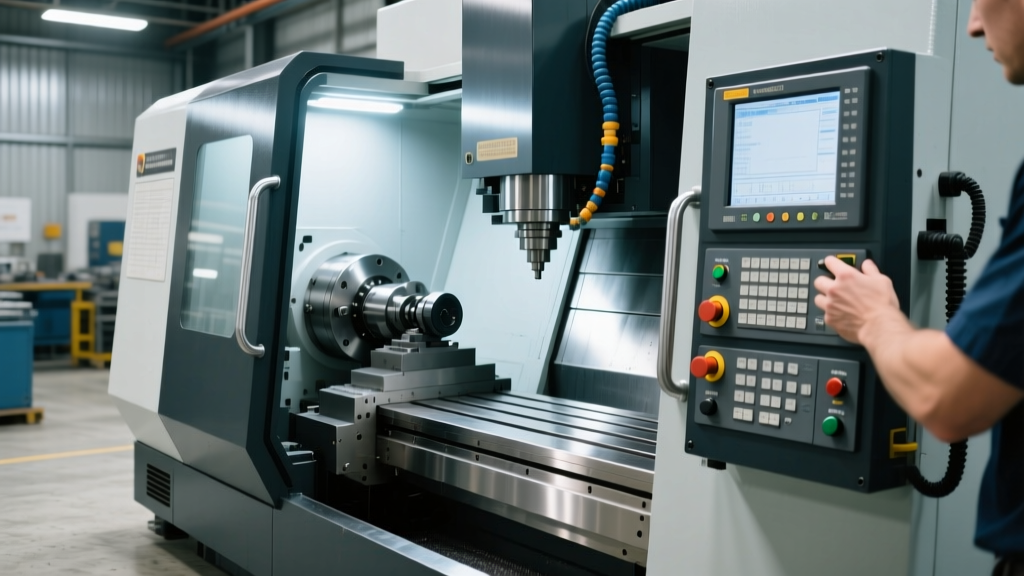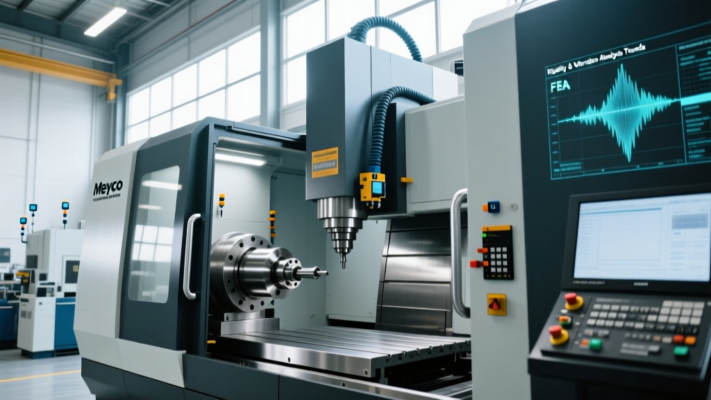
Meyco Machine and Tool Inc: Rigidity & Vibration Analysis Trends
Explore how Meyco Machine and Tool Inc leverages IoT, FEA, and active damping to master machine tool rigidity and vibration analysis in modern CNC shops.
Machine tool rigidity has historically been treated as a brute-force engineering problem: add more cast iron, increase the footprint, and dampen the structure with sheer mass. However, as aerospace and medical machining tolerances shrink below the 2-micron threshold, static mass is no longer sufficient. The modern paradigm relies on dynamic stiffness and real-time vibration analysis. Companies specializing in advanced custom tooling and precision machine integration, such as Meyco Machine and Tool Inc, have shifted toward sensor-driven diagnostics and topology-optimized structures to eliminate chatter at the source.
The Physics of Chatter: Why Static Rigidity Falls Short
Static rigidity measures a machine’s resistance to deflection under a constant load. While critical for maintaining geometric accuracy during heavy roughing, it does nothing to predict or prevent regenerative chatter—the self-excited vibration that occurs when the tool engages with a wavy surface left by a previous tooth pass. Chatter destroys surface finish, accelerates tool wear, and can catastrophically fracture carbide inserts.
According to Sandvik Coromant’s machining fundamentals, the key to avoiding chatter lies in maximizing dynamic stiffness, which is a function of both the machine’s natural frequency and its damping ratio. A standard gray cast iron machine base offers a damping ratio of approximately 0.001 to 0.005. By contrast, advanced epoxy granite (polymer concrete) bases utilized in high-precision jig grinders and custom milling platforms can achieve damping ratios of 0.05 to 0.08, absorbing vibrational energy up to ten times more effectively than traditional castings.
Data Highlight: The Cost of Unmanaged VibrationIn high-value aerospace structural milling (e.g., 7075-T6 aluminum monoliths), unmanaged chatter reduces material removal rates (MRR) by up to 40% as operators manually de-tune feed rates to avoid resonant frequencies. Implementing automated stability lobe mapping can recover this lost productivity, directly impacting spindle utilization metrics.
Meyco Machine and Tool Inc: Pioneering Dynamic Stiffness via FEA
When engineering custom fixtures, specialized machine bases, or complex multi-axis tooling assemblies, firms like Meyco Machine and Tool Inc utilize advanced Finite Element Analysis (FEA) to optimize structural topology before metal is ever cut. Using solvers like ANSYS Mechanical or Altair OptiStruct, engineers perform modal analysis to identify the first three natural frequencies of the tooling assembly.
Shifting the Natural Frequency
The goal of FEA-driven design is to push the fundamental natural frequency of the tool-machine-spindle system above the excitation frequencies generated during cutting. For a 5-flute end mill running at 12,000 RPM, the tooth-passing frequency is 1,000 Hz (12,000 / 60 * 5). If the tooling assembly has a natural frequency near 1,000 Hz, severe resonance will occur. By strategically ribbing the tooling body and removing non-essential mass (topology optimization), engineers can shift the natural frequency to 1,400 Hz, safely moving the system out of the resonant danger zone without adding weight that would degrade the spindle's acceleration capabilities.
Sensor Fusion and IoT Integration on the Shop Floor
Designing rigid tooling is only half the battle; verifying its performance under actual cutting loads requires advanced diagnostics. The integration of Industrial Internet of Things (IIoT) sensors has transformed vibration analysis from a post-process forensic tool into a real-time control mechanism.
| Diagnostic Metric | Traditional Approach (Pre-2020) | Modern IoT-Driven Approach (2026 Standard) |
|---|---|---|
| Measurement Hardware | Handheld data collectors; single-axis accelerometers. | Triaxial PCB Piezotronics (e.g., 352C33) permanently mounted via threaded studs. |
| Sampling Rate | 5 kHz (misses high-frequency spindle harmonics). | 50 kS/s to 100 kS/s, satisfying Nyquist criteria for 20,000+ RPM spindles. |
| Analysis Method | Post-process FFT (Fast Fourier Transform) via desktop software. | Edge-computed Short-Time Fourier Transform (STFT) yielding real-time spectrograms. |
| Action Threshold | Operator hears chatter and presses E-stop or overrides feed. | PLC automatically scales spindle speed by 2% to exit the unstable lobe. |
By mounting triaxial accelerometers directly on the spindle nose and the workpiece fixture, shops can capture vibration data in the X, Y, and Z planes simultaneously. The data is processed using edge-computing gateways that perform continuous Fast Fourier Transforms (FFT). This allows the CNC control to identify the exact frequency of emerging chatter and automatically adjust the spindle speed to move the tooth-passing frequency into a stable zone on the Stability Lobe Diagram (SLD).
Active Damping Systems: The 2026 Frontier
While passive damping (using viscoelastic materials or tuned mass dampers) remains common, the cutting edge of rigidity analysis involves active damping. Active systems use piezoelectric actuators or electromagnetic shakers embedded within the machine column or tool holder to generate a counter-vibration that is exactly 180 degrees out of phase with the detected chatter.
"Active damping doesn't just absorb energy; it actively cancels it. When paired with eddy-current sensors measuring real-time tool tip deflection, we are seeing sub-micron stability in overhang scenarios that would have been unmachinable a decade ago."
— Advanced Manufacturing Research Insights, NIST Advanced Manufacturing
Real-World Application: Milling Inconel 718
Consider the milling of Inconel 718, a nickel-based superalloy notorious for work-hardening and generating extreme cutting forces. A standard 20mm diameter, 4-flute solid carbide end mill with a 4D (80mm) overhang is highly susceptible to deflection. Without active damping, operators must limit the axial depth of cut (ap) to 1.0mm and radial depth (ae) to 0.5mm to avoid chatter, resulting in agonizingly slow cycle times.
By deploying an active damping tool holder equipped with internal displacement sensors, the system detects the onset of harmonic vibration at 4,500 RPM and instantly commands the piezoelectric actuators to stiffen the tool shank dynamically. This allows the shop to increase the axial depth of cut to 3.0mm and push the spindle speed to 5,200 RPM, effectively tripling the material removal rate while maintaining a surface roughness (Ra) of 0.4 µm. For deeper insights into managing difficult-to-machine materials, the Society of Manufacturing Engineers (SME) provides extensive technical papers on superalloy machining dynamics.
Actionable Framework for Upgrading Shop Floor Diagnostics
Implementing a modern vibration analysis protocol does not require replacing your entire CNC fleet. Follow this phased approach to integrate rigidity analytics into your existing workflow:
- Baseline Modal Tap Testing: Purchase or rent an instrumented impact hammer and a triaxial accelerometer. Perform tap tests on your most critical tooling assemblies (especially long-reach boring bars and extended end mills) to map their natural frequencies. Build a digital library of these frequencies in your CAM software.
- Generate Stability Lobe Diagrams (SLDs): Use the modal data to generate SLDs for your specific tool-machine combinations. Program your CNC spindle speeds to align with the "sweet spots" (the peaks of the lobes) where the phase shift between successive tooth passes cancels out vibration.
- Deploy Permanent Acoustic Emission (AE) Sensors: Instead of relying solely on accelerometers, install AE sensors on the machine table. AE sensors detect high-frequency stress waves (100 kHz to 1 MHz) generated by micro-chipping and tool wear long before macro-vibration (chatter) becomes audible or measurable by standard accelerometers.
- Integrate Edge Analytics: Connect your sensor arrays to an edge gateway (e.g., Siemens Industrial Edge or FANAI) capable of running machine learning algorithms. Train the model to recognize the specific acoustic signature of tool breakage versus normal roughing chatter, enabling automated feed-holds that save thousands of dollars in scrapped aerospace components.