How Machine Alignment Tools Prevent Lubrication Failures
Discover how precision machine alignment tools optimize CNC lubrication systems, prevent way oil shear, and dictate accurate maintenance schedules.
The Tribology of Geometric Precision
In CNC machining, geometric alignment and tribological performance are inextricably linked. While maintenance teams often treat machine geometry and fluid power as separate disciplines, the physical reality of a machine tool dictates otherwise. When linear axes, ballscrews, or spindle housings fall out of tolerance, the resulting uneven load distribution fundamentally alters the hydrodynamic lubrication regime. Utilizing precision machine alignment tools is not merely a geometric exercise; it is the foundational prerequisite for establishing a viable, optimized lubrication schedule.
⚠️ Critical Warning: Setting a volumetric lubrication schedule on a misaligned CNC mill guarantees premature way cover and ballscrew failure. Misalignment increases localized Hertzian contact stress, which spikes friction and generates localized heat. This heat drops the viscosity of ISO VG 68 way oils below the critical threshold required to maintain a 10-micron fluid film, forcing the system into boundary lubrication and causing catastrophic stick-slip wear.The Physics of Misalignment-Induced Lubricant Shear
To understand why alignment dictates lubrication schedules, we must examine the fluid dynamics of a standard box-way or linear guide system. A properly aligned X-axis distributes the carriage load evenly across the entire surface area of the way. Under these conditions, a standard Bijur or SKF Lincoln one-shot lubrication system delivering 4 seconds of pump time every 60 seconds is sufficient to replenish the oil wedge.
However, if the axis is misaligned by just 0.003 inches over a 40-inch travel—a common deviation in machines that have suffered a minor crash or foundation settling—the load shifts entirely to the leading or trailing edge of the way insert. This edge-loading creates two distinct lubrication failures:
- Thinning of the Oil Wedge: The extreme localized pressure (often exceeding 15,000 PSI at the contact patch) physically squeezes the lubricant out of the load zone.
- Thermal Shearing: The increased friction coefficient generates localized temperatures exceeding 140°F (60°C). Because way oils rely on a high Viscosity Index (VI) to resist thermal thinning, this localized heat causes the oil to shear, losing its tackiness additives (such as polymethacrylates) and failing to adhere to the vertical Y and Z axes.
Consequently, a machine that is out of alignment will consume lubricant at twice the normal rate while simultaneously suffering from oil starvation at the critical load points. According to extensive field data on rotating and linear equipment, correcting geometric misalignment using laser-based machine alignment tools can extend lubricant life and bearing/way life by up to 50%.
Selecting Machine Alignment Tools for Baseline Verification
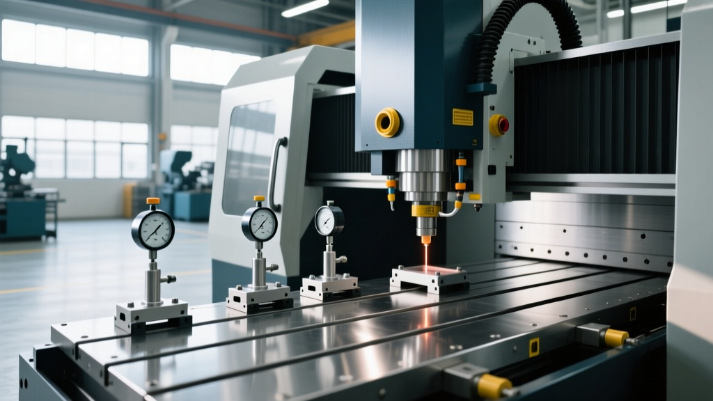
Before programming the PLC timer for your machine's automatic lubrication pump, you must verify the geometric baseline. The choice of alignment tool dictates the confidence level of your subsequent lubrication schedule. Below is a technical comparison of industry-standard alignment equipment used in 2026 for CNC verification.
| Alignment Tool Category | Specific Model Example | Resolution / Accuracy | Approx. Cost (2026) | Lubrication Schedule Impact |
|---|---|---|---|---|
| Precision Machinist Level | Starrett 199Z (12-inch) | 0.0005" / 12" | $850 - $1,100 | Verifies foundation twist; allows standard OEM lube intervals. |
| 2-Axis Laser Shaft Aligner | Hamar Laser X-Align Pro | 0.0001" / 10" | $14,000 - $16,500 | Maps ballscrew parallelism; critical for optimizing metering unit (MU) flow rates. |
| Laser Interferometer | Renishaw XL-80 | 1 nm linear resolution | $65,000+ | Measures dynamic straightness under load; enables condition-based, extended lube schedules. |
Adjusting Volumetric Lube Schedules Based on Alignment Data
Once alignment data is captured, the CNC maintenance engineer must adjust the positive metering lubrication system (e.g., Bijur, Met One-Shot, or SKF Lincoln) to match the physical reality of the machine. Standard OEM settings assume perfect factory alignment. Field conditions require dynamic adjustments.
The Alignment-to-Lube Decision Matrix
Use the following framework to program your lubrication pump timer (Pump ON time : Pump OFF time) based on the measured deviation in axis parallelism and squareness.
- Condition A: Verified Precision (Deviation < 0.0002" over full travel)
Action: Extend the OFF cycle to conserve way oil and reduce environmental misting.
Recommended Setting: 4 seconds ON / 90 seconds OFF. Ensure ISO VG 68 oil with high tackiness additives (e.g., Mobil Vactra Oil No. 2) is used to maintain the film during the extended dry cycle. - Condition B: Acceptable Field Tolerance (Deviation 0.0002" to 0.0008")
Action: Maintain standard OEM protective scheduling. The minor edge loading is mitigated by standard fluid replenishment.
Recommended Setting: 4 seconds ON / 60 seconds OFF. - Condition C: Critical Misalignment (Deviation > 0.0008" or binding detected)
Action: Increase lubrication frequency immediately to act as a boundary-layer protectant while scheduling a mechanical realignment. Do not operate in high-speed rapid traverse (G00) under this condition.
Recommended Setting: 8 seconds ON / 30 seconds OFF. Monitor reservoir levels daily, as consumption will increase by approximately 45%.
Case Profile: Haas VF-2 Y-Axis Way Lube Optimization
Consider the ubiquitous Haas VF-2 vertical machining center. The Y-axis on this machine utilizes a specific network of positive metering units (MUs) to distribute oil to the way surfaces and the ballscrew nut. A common issue in aging VF-2 models is Y-axis stick-slip during heavy contouring, often misdiagnosed as a failing ballscrew or degraded way oil.
In a documented maintenance scenario, a shop experienced Y-axis stick-slip and replaced the ISO VG 68 oil with a synthetic alternative, which failed to resolve the issue. The maintenance team then deployed a dual-laser machine alignment tool to map the Y-axis travel relative to the X-axis. The laser data revealed a 0.0015" yaw error in the Y-axis saddle, caused by uneven wear on the gib and a misadjusted wedge.
Because of this yaw error, the leading edge of the Y-axis saddle was physically scraping the way oil off the cast iron surface before the trailing edge could ride on it. The standard 4:60 lube schedule was entirely inadequate for this localized scraping action. By first adjusting the Y-axis gib to eliminate 80% of the yaw error (verified via laser), and then temporarily increasing the lube cycle to 6:45 to flush out the microscopic wear debris generated during the scraping phase, the stick-slip was eliminated. Once flushed, the schedule was returned to an optimized 4:75, saving the shop roughly 14 gallons of way oil annually per machine.
Diagnostic Troubleshooting: Alignment vs. Lubrication
When diagnosing machine tool anomalies, technicians must evaluate alignment and lubrication simultaneously. Use this diagnostic matrix to isolate the root cause of axis drive faults.
| Symptom | Lubrication System Check | Alignment Tool Verification | Corrective Action |
|---|---|---|---|
| Servo motor runs hot; following error alarms during direction reversal. | Check MU flow pins. Verify pump pressure reaches 250 PSI during the ON cycle. | Use a dial indicator or laser to check for axis binding or preload loss in the thrust bearings. | If MUs are flowing but binding exists, realign the ballscrew thrust housing. Misalignment is causing mechanical resistance that oil cannot cure. |
| Vertical axis (Z) drops slightly when the pump cycles. | Way oil viscosity is too low, or tackiness additive has sheared. | Check column squareness to the bed using a precision level. | Flush system with fresh ISO VG 68. If column is out of square, the Z-axis gib is over-tightened to compensate, requiring excessive lube to overcome friction. |
| Way covers tear prematurely; oil pools at one end of the bed. | Metering units are blocked; oil is bypassing through the path of least resistance. | Verify bed leveling and foundation twist using a 0.0005" precision level. | Clear MU blockages. Re-level the machine foundation. Gravity will defeat the capillary action of way oil if the bed is twisted. |
Final Integration Protocol
Integrating geometric verification with fluid management requires a shift in maintenance culture. Machine alignment tools should not be locked away for annual calibration checks; they must be deployed whenever a lubrication schedule is altered, a machine is relocated, or a crash event occurs. By treating the physical alignment of the machine as the primary variable in your tribological equation, you eliminate the guesswork from CNC maintenance, ensuring that every drop of way oil contributes directly to precision machining and extended asset life. For deeper technical standards on machinery alignment practices, consult the guidelines provided by SKF's machinery alignment engineering resources, which detail the direct correlation between geometric tolerance and bearing/lubricant lifecycle.