Japan Machine Tool Innovation: 2026 Vibration Analysis Trends
Explore how Japan machine tool builders leverage active damping, AI sensor fusion, and advanced castings to eliminate chatter and maximize rigidity in 2026.
The Shift from Mass to Active Rigidity in Japanese Machining Centers
Historically, the Japan machine tool industry equated structural rigidity with sheer mass. Builders relied on heavily ribbed, oversized Meehanite cast iron structures to absorb cutting forces and dampen harmonic vibrations. While effective, this approach imposed severe limitations on rapid traverse rates, increased energy consumption, and expanded the machine footprint. In 2026, the paradigm has shifted decisively toward optimized, actively damped structures that maintain nanometer-level accuracy without the penalty of excessive weight.
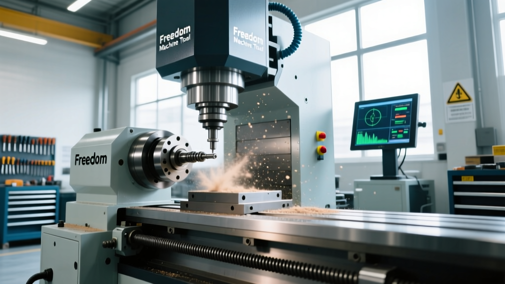
Modern Japanese vertical machining centers (VMCs) and 5-axis platforms now utilize advanced Finite Element Analysis (FEA) to map vibration modes before a single casting is poured. By strategically placing high-damping epoxy granite (polymer concrete) cores within critical structural nodes—such as the column-to-bed junction and spindle head—engineers achieve a damping coefficient up to 8 times higher than standard FC300 grade cast iron. This hybrid material approach allows for aggressive acceleration and deceleration profiles while keeping the tool tip deviation under 3 microns during heavy roughing cycles.
2026 Market Insight: According to data from the Japan Machine Tool Builders' Association (JMTBA), over 65% of new high-speed 5-axis machining centers exported from Japan now feature some form of hybrid passive-active damping architecture, a 40% increase from 2022 baseline levels.Sensor Fusion and Edge-AI Chatter Suppression
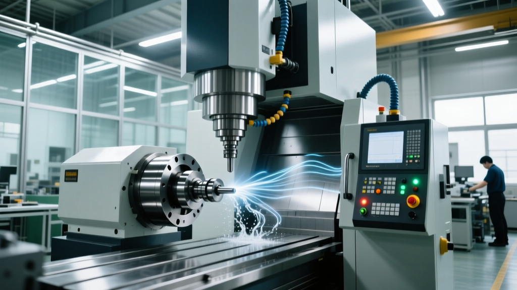
The most significant technological leap in Japan machine tool vibration analysis is the integration of edge-computing AI directly into the CNC controller. Regenerative chatter—the self-excited vibration that destroys surface finish and tool life—occurs when the phase shift between consecutive tool passes aligns with the natural frequency of the machine-tool-workpiece system.
Instead of relying solely on the operator's ear to detect chatter, 2026-era Japanese controllers utilize sensor fusion. Triaxial piezoelectric accelerometers mounted directly on the spindle housing sample vibration data at 20 kHz. This raw time-domain data is instantly converted into the frequency domain using Fast Fourier Transform (FFT) algorithms running on dedicated edge-processing chips.
Real-Time Stability Lobe Adaptation
When the FFT detects a spike in amplitude at a specific natural frequency (e.g., 1,450 Hz), the AI cross-references the machine's pre-mapped Stability Lobe Diagram (SLD). Within 4 milliseconds, the controller autonomously overrides the programmed spindle speed, shifting the RPM by 2-5% to move the cutting frequency into a stable 'sweet spot' between the lobes. This closed-loop suppression eliminates chatter without requiring manual intervention or sacrificing material removal rates (MRR).
Comparative Matrix: Damping Technologies in Modern VMCs
Understanding the hierarchy of vibration control is critical for specifying the right equipment for aerospace and medical machining applications. The following matrix breaks down the primary rigidity technologies deployed in current Japanese machining centers.
| Technology | Mechanism of Action | Reaction Time | Cost Premium (Est.) | Ideal Application |
|---|---|---|---|---|
| Monolithic Cast Iron | Internal friction of graphite flakes in FC300 iron | Passive / Instant | Base Price | General 3-axis milling, heavy roughing |
| Epoxy Granite Core | Viscoelastic polymer matrix absorbs high-frequency waves | Passive / Instant | + $12,000 - $18,000 | High-speed finishing, graphite milling |
| Tuned Mass Dampers (TMD) | Internal counter-mass oscillates out-of-phase to cancel vibration | Passive / Tuned | + $8,000 - $15,000 | Deep cavity milling, long-reach tooling |
| Active Piezoelectric | Actuators apply counter-force based on real-time sensor feedback | < 2 milliseconds | + $35,000 - $60,000 | Thin-wall aerospace structures, micro-machining |
Tooling Integration: Extending Rigidity Beyond the Spindle
Machine base rigidity is rendered useless if the cutting tool acts as a tuning fork. The Japan machine tool ecosystem relies heavily on advanced tooling interfaces and damped holders to complete the vibration control loop. The transition from standard CAT40/BT40 tapers to dual-contact interfaces (such as BIG-PLUS or HSK-A63) provides simultaneous face-and-taper contact, increasing radial rigidity by up to 300% at the spindle nose.
For deep-hole boring and turning operations on mill-turn centers, passive damping within the toolholder is mandatory. As detailed in the Sandvik Coromant machining knowledge base, modern damped boring bars utilize a heavy metal core suspended in a specialized elastomeric fluid. This internal tuned mass damper allows for overhang ratios of up to 14 times the bar diameter (14xD) while maintaining a stable cut. When pairing a Japanese 5-axis mill-turn center with these adaptive tooling systems, shops can achieve surface finishes of 0.8 Ra in deep-cavity Inconel 718 applications that would previously induce catastrophic chatter.
"The machine tool is only half of the dynamic system. In 2026, analyzing the Frequency Response Function (FRF) of the tool-holder-spindle assembly via impact testing is no longer optional for Tier 1 aerospace suppliers; it is a baseline requirement for process validation."
Actionable Vibration Diagnostics for Shop Floors
While OEMs integrate advanced sensors, shop floor maintenance teams must proactively monitor the degradation of mechanical rigidity. Vibration analysis is the most reliable predictor of ball screw preload loss and linear guide wear. Implementing a standardized diagnostic workflow ensures that the machine's original damping characteristics are preserved.
Step-by-Step Diagnostic Workflow
- Establish the Baseline (ISO 10816-3 Compliance): Upon installation, mount a calibrated triaxial accelerometer on the spindle housing and table. Record the baseline vibration velocity in mm/s RMS. According to ISO 10816-3 for Group 2 machines (medium CNCs), a new machine on a rigid foundation should operate in Zone A (below 1.12 mm/s RMS).
- Monitor the Z-Axis Ball Screw Preload: Loss of ball screw preload is a primary cause of Z-axis chatter during plunge milling. Perform a monthly reversal error test using a laser interferometer. If backlash exceeds 4 microns, or if vibration in the Z-axis exceeds 2.8 mm/s RMS (entering ISO Zone C), the ball screw nuts require immediate preload adjustment or replacement.
- Inspect Linear Guide Carriages: Recirculating ball linear guides offer high speed but lower inherent damping than box ways. Check for harmonic squeal or high-frequency spikes (above 2,000 Hz) in the FFT data. This indicates a lack of proper lubrication film thickness or brinelling on the guide rails, which severely compromises dynamic stiffness.
- Validate Spindle Drawbar Force: A weak drawbar allows the toolholder to micro-fret inside the taper under heavy radial loads, generating high-amplitude, low-frequency vibrations. Use a calibrated drawbar force gauge annually; a 40-taper spindle should maintain a minimum of 2,500 lbs (11 kN) of retention force.
By combining the inherent structural advantages of Japanese casting engineering with rigorous, data-driven vibration analysis protocols, manufacturing facilities can push the boundaries of material removal rates while securing the tool life and surface integrity required for modern precision components. For further technical specifications on spindle dynamics and structural damping, refer to the engineering whitepapers available via Makino's global technical resources.