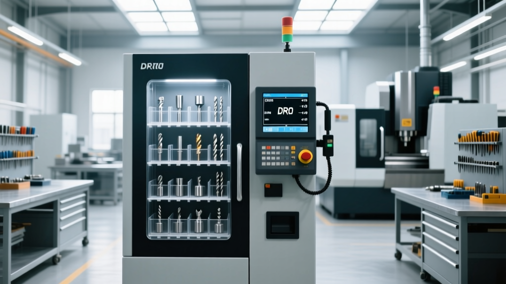
Integrating Industrial Tool Vending Machines with DRO Readouts
Learn how operators can sync industrial tool vending machines with DRO readouts and CNC controls to eliminate offset errors and prevent spindle crashes.
The modern machine shop floor in 2026 operates as a synchronized network where inventory control and machining precision are inextricably linked. While many view industrial tool vending machines purely as cost-control mechanisms to reduce carbide consumption, their true value emerges when integrated directly into the operator's setup workflow. For shops running manual mills, lathes, or retrofitted CNC equipment, the physical act of dispensing a tool is the critical first step in establishing the metrology chain that ends at the Digital Read Out (DRO) or machine control system.
Operator training must bridge the gap between automated inventory dispensing and precise tool offset entry. A mismatch between the physical tool pulled from an AutoCrib or CribMaster unit and the geometry values entered into a Newall or Sony DRO will inevitably result in scrapped parts, broken taps, or catastrophic spindle crashes. This guide details the exact workflows, control system fundamentals, and best practices required to synchronize tool vending with DRO readouts.
The Metrology Chain: From Vending to Spindle
When an operator badges into an automated vending system to pull a 1/2-inch Kennametal HARVI III end mill, they are not just acquiring a cutting tool; they are acquiring a specific set of geometric data. The physical tool must match the digital record exactly. If the vending machine dispenses a 4-flute AlTiN coated end mill, but the operator accidentally grabs a 3-flute TiAlN variant sitting loose in the return bin, the Cutter Radius Compensation (CRC) entered into the DRO will be incorrect.
According to Sandvik Coromant's machining fundamentals, even a 0.001-inch deviation in tool diameter or edge preparation can drastically alter cutting forces, leading to chatter, poor surface finish, and accelerated tool wear. Therefore, the vending machine is the first checkpoint in the quality assurance process.
Mastering DRO and Control System Offsets
Whether you are operating a manual Bridgeport equipped with a Newall DP700 DRO or a CNC lathe with a Fanuc control, understanding how the system calculates tool geometry is non-negotiable for operators.
Tool Length (Z-Axis) vs. Cutter Radius Compensation (X/Y-Axis)
On a manual mill with a 2-axis DRO, operators typically use the Z-axis quill readout to establish depth. However, when switching from a spot drill to a tapping operation, the physical length of the tools differs. Operators must calculate the delta between the two tools and adjust the DRO's incremental datum accordingly.
On 3-axis CNC systems or advanced DROs, Tool Length Offsets (TLO) allow the control to automatically adjust the Z-axis zero point based on the tool's specific stick-out. If the vending machine dispenses a CAT40 toolholder with a 3.5-inch gauge length, but the operator inputs 3.05 inches into the control's offset page, the machine will drive the spindle 0.45 inches deeper than programmed, crushing the tool into the vise.
⚠️ CRITICAL WARNING: The 'Ghost Tool' HazardA 'ghost tool' occurs when a tool is returned to the vending machine, but the previous operator fails to clear its offset from the DRO or CNC control memory. The next operator assumes the default zero point is accurate, leading to immediate Z-axis crashes. Always mandate a 'Clear All Offsets' protocol at the start of every new job setup.
Best Practices at the Industrial Tool Vending Machine
Proper interaction with the vending hardware ensures the tooling arrives at the machine tool in pristine, measurable condition.
- Verify the Dispense Coil Pitch: Vending machines use spiral coils to push tools forward. Ensure the machine is calibrated so that a 3/4-inch shank end mill is dispensed from a coil designed for 3/4-inch diameters. Using a coil that is too wide will cause the tool to drop and chip its carbide flutes against the metal dispensing bin.
- Inspect the Edge Prep: Before leaving the vending station, visually inspect the cutting edges under a magnifying lamp. Look for micro-chips on the insert or end mill flutes. A damaged tool will yield false readings when touched off on the machine.
- Scan the Data Matrix Code: Modern tooling features laser-etched Data Matrix codes. Use the vending machine's integrated scanner or a handheld shop-floor terminal to pull the exact CAD geometry and recommended feeds/speeds directly to the operator's tablet before walking to the machine.
Step-by-Step: Vending to DRO Touch-Off Workflow
To eliminate setup errors, operators should follow this standardized workflow when moving from the tool crib to the machine control:
- Dispense and Verify: Pull the required toolholder and cutting tool from the vending machine. Verify the part number on the physical box matches the job traveler.
- Assemble and Torque: Assemble the tool in the toolroom using a calibrated torque wrench. For a 1/2-inch end mill in a Weldon flat holder, torque the set screw to exactly 35 ft-lbs to prevent tool pull-out during heavy roughing.
- Establish Machine Datum: Mount the workpiece and use an edge finder or Haimer 3D Sensor to establish the X and Y zero points on the DRO. Press the 'DATUM' or 'ZERO' button on the Newall or Sony readout to lock the absolute coordinates.
- Z-Axis Touch-Off: Mount the newly vended tool in the spindle. Use a Z-axis presetter block (e.g., a 2-inch Haimer block) on the finished top surface of the part. Lower the quill until the indicator reads zero.
- Input the Offset: On the DRO, account for the 2-inch height of the presetter block. If the DRO is in Absolute mode, input the Z-coordinate as -2.0000 inches (or the metric equivalent). If using a CNC control, enter this value into the Tool Length Geometry offset page for that specific tool number.
- Execute Verification Cut: Take a light skim cut (0.005 inches deep) on a scrap area of the part. Measure the actual depth with a calibrated micrometer and adjust the DRO wear offset by the delta between the commanded depth and the measured depth.
Comparison Matrix: Manual Tool Crib vs. Automated Vending Integration
| Feature | Manual Tool Crib | Automated Vending (AutoCrib/CribMaster) |
|---|---|---|
| Tool Geometry Data | Manual lookup in catalogs; high error rate | Digital display at dispense; exact stick-out and diameter data provided |
| Offset Tracking | Paper travelers; easily lost or misread | Networked integration pushes offsets directly to CNC/DRO via shop Wi-Fi |
| Tool Condition | Returned tools mixed with new; high crash risk | Forces operators to select 'New' or 'Regrind' status upon return |
| Setup Time | 15-25 minutes per complex job setup | 5-10 minutes; tools are kitted and dispensed in sequence |
Troubleshooting Edge Cases and DRO Drift
Even with perfect vending integration, environmental and mechanical factors can compromise DRO accuracy. Operators must be trained to identify and correct these edge cases.
"In 2026, thermal compensation is standard on high-end CNCs, but manual machines with glass-scale DROs are still highly susceptible to ambient temperature shifts. A 10-degree Fahrenheit drop in the shop overnight can cause the cast-iron column of a manual mill to contract, shifting the Z-axis zero point by up to 0.0008 inches. Always re-verify your Z-datum with a presetter block after the machine has been idle for more than four hours."
— Master Toolmaker, Precision Aerospace Job Shop
Common DRO and Vending Discrepancies
- The 'Regrind' Radius Error: The vending machine dispenses a regridded end mill. The operator inputs the original factory diameter (e.g., 0.5000") into the DRO's CRC page. The actual tool diameter is 0.4985". The resulting profile will be oversized by 0.0015". Fix: Mandate that all regrinds are measured on a Zoller presetter, and the exact measured diameter is taped to the toolholder before it is placed in the vending machine's return locker.
- Scale Contamination: Coolant mist and fine cast-iron dust can settle on the exposed glass scales of a DRO, causing the readout to 'jump' or lose its absolute position. Fix: Operators must wipe down DRO scale covers with a lint-free cloth and isopropyl alcohol at the start of every shift, ensuring the reader head tracks smoothly.
- Vending Machine Locker Door Calibration: For large tooling like CAT50 face mills, vending machines use secure locker doors rather than spiral coils. If the locker door sensor is misaligned, the system may register the tool as 'dispensed' before the door fully opens, prompting the operator to pull against the locking mechanism, potentially damaging the toolholder's retention knob.
Summary Checklist for Operators
To ensure seamless integration between inventory management and machine tool control, operators should memorize this pre-flight checklist:
- Verify the physical tool matches the digital vending dispense record.
- Inspect cutting edges for micro-chips before leaving the crib.
- Clear all previous tool offsets from the DRO/CNC control memory.
- Establish X/Y datums using a calibrated edge finder or 3D sensor.
- Perform a Z-axis touch-off using a certified presetter block.
- Execute a verification skim cut and adjust the wear offset based on micrometer measurements.
By treating the industrial tool vending machine as the foundational step in the metrology process, rather than just a storage closet, machine shops can drastically reduce setup times, eliminate catastrophic crashes, and maintain the tight tolerances demanded by modern manufacturing.