Operator Guide: Machine Tool Monitoring via DRO & Control Systems
Learn how operators use advanced DRO readouts and CNC control telemetry for effective machine tool monitoring to prevent crashes and reduce scrap.
The Evolution of the Operator Interface: From Passive Reading to Active Monitoring
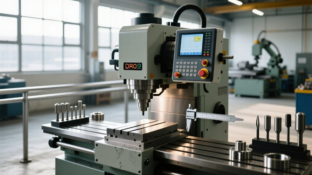
Historically, a Digital Read Out (DRO) on a manual milling machine or lathe served a single, passive function: displaying the X, Y, and Z axis positions. Operators relied entirely on tactile feedback, sound, and visual cues to assess cutting conditions. As of 2026, the paradigm has shifted. Modern Fagor Automation digital readouts and advanced CNC control interfaces have transformed the operator screen into a comprehensive machine tool monitoring hub. By integrating position feedback with spindle load telemetry, thermal compensation algorithms, and vibration detection, operators can now predict tool failure, prevent crashes, and hold sub-0.0005-inch tolerances over long production runs.
Effective machine tool monitoring requires operators to move beyond simply zeroing an axis. It demands a systematic approach to interpreting control system data, establishing baselines, and recognizing the subtle anomalies that precede catastrophic tool failure or out-of-tolerance parts.
⚠️ Critical Safety Warning: Never rely solely on DRO positioning for crash prevention during automated or semi-automated cycles. DRO scales measure table position, not tool tip deflection. A 0.003-inch tool deflection under heavy radial load will not register on a standard glass or magnetic scale, leading to dimensional errors even if the DRO reads perfectly on target.Upgrading the Feedback Loop: Scale Technologies and Contamination Resistance
The foundation of any position-based machine tool monitoring system is the linear scale. If the scale provides faulty data, the control system's compensation algorithms will overcorrect, causing axis oscillation and poor surface finishes. Operators and shop managers must select scale technology based on the machine's environment.
Optical Glass vs. Magnetic Inductive Scales
Traditional optical glass scales offer high resolution (down to 0.0001 inches) at a low cost ($150–$300 per axis). However, they are highly susceptible to coolant ingress and fine swarf contamination. When coolant mist coats the glass, the optical reader misinterprets the light refraction, causing 'ghosting' or sudden axis jumps on the DRO.
For rigorous machine tool monitoring in wet environments, Newall Spherosyn magnetic scales represent the industry standard. Priced between $450 and $850 per axis, these inductive scales operate flawlessly even when completely submerged in cutting fluid or packed with cast iron dust. They carry an IP67 rating and eliminate the false-positive position errors that plague optical scales in heavy roughing environments.
Control System Telemetry: Beyond X-Y-Z Coordinates
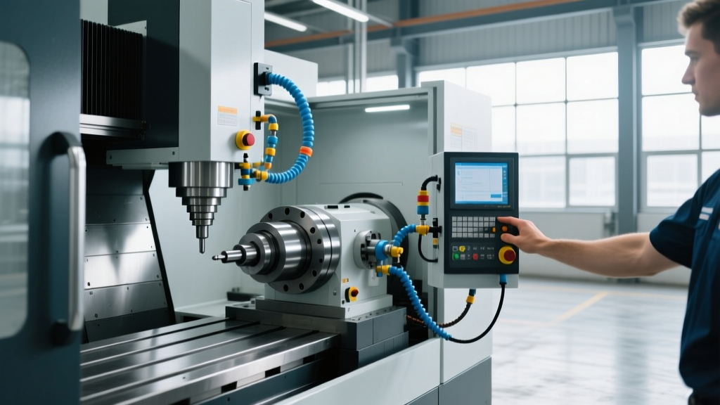
Modern CNC controls, such as the Heidenhain TNC7 control architecture, embed machine tool monitoring directly into the operator's primary workflow. Instead of requiring third-party IoT dashboards, the control natively tracks:
- Spindle Load Percentage: Real-time amperage draw compared to the motor's rated capacity.
- Axis Torque Limits: Servo motor torque required to maintain programmed feed rates.
- Thermal Growth Compensation: Algorithmic adjustments based on machine casting temperature sensors.
- Vibration Harmonics: Accelerometer data used to detect chatter before it marks the workpiece.
DRO & Control Monitoring Capabilities Matrix
| Monitoring Feature | Basic 2-Axis DRO (e.g., Easson) | Advanced 3-Axis DRO (e.g., Fagor INOVA-360) | Full CNC Control (e.g., Fanuc 0i-F Plus / Heidenhain TNC7) |
|---|---|---|---|
| Position Feedback Resolution | 0.0002" / 0.005mm | 0.0001" / 0.001mm | 0.00004" / 0.001μm |
| Spindle Load Tracking | None | Analog Meter Integration (Retrofit) | Native Digital Telemetry (Real-time %) |
| Thermal Drift Compensation | None | Manual Operator Input | Automated via Casting Thermistors |
| Tool Life Management | None | Basic Cycle Count | Time, Wear, and Load-Based Tracking |
| IoT / MTConnect Export | No | Limited (Serial/USB) | Native Ethernet / MTConnect / OPC-UA |
| Estimated 2026 Retrofit Cost | $800 - $1,200 | $2,500 - $4,000 | $15,000+ (Full Machine Integration) |
Step-by-Step Operator Workflow for Real-Time Monitoring
To leverage machine tool monitoring effectively, operators must establish baselines at the start of every shift or new setup. Follow this protocol to ensure the control system and DRO are accurately reflecting the physical state of the machine.
- Establish the Air-Cutting Baseline: Before engaging the workpiece, run the spindle at the programmed RPM and rapid the axes through the intended toolpath. Note the baseline spindle load (typically 5% to 12% on a 15HP motor) and axis servo torque. This is your 'zero' state.
- Monitor Thermal Growth on the Z-Axis: Cast iron and steel machine columns expand as heat transfers from the spindle bearings and way friction. Ductile iron has a coefficient of thermal expansion of roughly 6.5 × 10⁻⁶ in/in/°F. On a machine with a 24-inch Z-axis column, a 15°F temperature rise during the first hour of operation will cause the spindle nose to grow downward by approximately 0.0023 inches. Operators using manual DROs must intentionally offset the Z-axis by this calculated drift during warm-up, while CNC operators should verify that the control's thermal compensation macro is actively adjusting the Z-axis work coordinate.
- Track Spindle Load Delta During Roughing: When taking a heavy roughing cut (e.g., 0.200" radial depth of cut in 4140 steel), the spindle load should stabilize at a predictable percentage (e.g., 65%). If the load begins to creep upward by 5-10% over successive passes without a change in programmed feed or depth, the tool is experiencing built-up edge (BUE) or flank wear. This is the operator's cue to index the insert before it catastrophically fails and damages the workpiece.
"The most expensive mistake an operator can make is ignoring a 5% creep in spindle load. That creeping amperage is the physical signature of a dulling edge generating excess heat, which will inevitably lead to work-hardening the material and snapping the tool on the next pass." — Senior Manufacturing Engineer, Tier 1 Aerospace Machine Shop
Troubleshooting Feedback Anomalies and Edge Cases
Machine tool monitoring systems are only as reliable as the data they ingest. When the DRO or CNC control displays erratic behavior, operators must diagnose the root cause rather than simply resetting the system.
Symptom: DRO 'Ghosting' or Sudden Axis Jumps
The Cause: Electromagnetic Interference (EMI) or scale contamination. If the machine was recently retrofitted with a Variable Frequency Drive (VFD) for the coolant pump or spindle, unshielded power cables running parallel to the DRO scale signal cables will induce voltage spikes. Alternatively, fine aluminum swarf has packed into the scale's wiper seal.
The Fix: Reroute DRO signal cables at least 6 inches away from VFD power lines, or wrap signal cables in copper braided shielding. For contamination, flush the scale with isopropyl alcohol (never use harsh solvents that degrade the rubber wiper seals) and replace the wiper gaskets if they show signs of compression set.
Symptom: Spindle Load Spikes Without Increased Depth of Cut
The Cause: Loss of coolant lubricity. If the machine tool monitoring system shows a 20% increase in cutting forces despite identical toolpaths and material, the issue is often chemical, not mechanical. Tramp oil infiltration or a drop in coolant concentration below 6% destroys the fluid's boundary lubrication properties, causing massive friction at the shear zone.
The Fix: Test the coolant concentration immediately using a refractometer. Skim tramp oil, adjust the concentration back to the manufacturer's specified 8-10% range, and verify the nozzle is delivering flood coolant directly into the cutting zone, not just washing over the top of the part.
Symptom: Axis Servo Lag Error During High-Speed Contouring
The Cause: Way lubrication failure or gib misalignment. The control system monitors the torque required to move the axis. If the one-shot way lube system has a clogged metering valve, the cast iron way surfaces will experience boundary friction, causing the servo motor to work harder and lag behind the commanded position.
The Fix: Manually trigger the way lube pump and verify that oil is weeping from all way covers. Check the machine's lubrication pressure switch alarm history in the control diagnostics page.
Operator Takeaways for 2026
Mastering machine tool monitoring via DRO and control systems requires treating the screen as a diagnostic instrument, not just a digital ruler. By understanding thermal expansion coefficients, maintaining scale integrity against EMI and swarf, and actively tracking spindle load deltas, operators can transition from reactive button-pushers to proactive process engineers. Invest in magnetic scales for wet environments, establish strict air-cutting baselines, and never ignore a creeping load meter.