DRO Maintenance for Machining the Lewis Machine and Tool Lower
Learn the exact DRO and control system maintenance schedules required to hold tight tolerances when machining the Lewis Machine and Tool lower receiver.
Manufacturing the Lewis Machine and Tool lower receiver—particularly their ambidextrous MARS-L and CQB platforms—demands uncompromising dimensional stability. While primary 5-axis CNC milling centers handle the bulk of the monolithic pocketing, secondary operations, manual fixture adjustments, and CMM-style inspection stations rely heavily on Digital Read Out (DRO) systems and secondary machine tool controls. When machining aerospace and defense-grade aluminum forgings (like 7075-T6), a DRO axis drift of just 0.0005 inches can cause buffer tube thread concentricity failures or mag-well interference issues, resulting in scrapped batches.
📊 Tolerance vs. DRO Resolution MatrixTo maintain mil-spec compliance for the Lewis Machine and Tool lower, your DRO and control system feedback loops must exceed the part tolerance by a minimum ratio of 10:1.
- Buffer Tube Thread Concentricity: Part Tolerance ±0.001" | Required DRO Resolution: 0.0001" (0.1 micron)
- Mag Well Pocket Width: Part Tolerance ±0.002" | Required DRO Resolution: 0.0002"
- Trigger Pin Hole True Position: Part Tolerance ±0.0005" | Required DRO Resolution: 0.00005"
Core DRO and Control Systems in Lower Receiver Production
In a high-volume defense manufacturing environment, the choice of encoder technology dictates the maintenance schedule. For machining the Lewis Machine and Tool lower, shops generate massive amounts of fine aluminum swarf and use aggressive water-soluble coolants.
Optical Encoders (e.g., Heidenhain LS Series): These offer nanometer-level resolution but are highly susceptible to coolant mist and aluminum fines. If a single micron of swarf breaches the scale housing, the read head will scatter light, causing the DRO display to jump or freeze during critical secondary drilling operations.
Magnetic Encoders (e.g., Newall Spherosyn): Widely considered the industry standard for harsh aluminum-machining environments. Because they rely on magnetic flux rather than light, they are completely immune to coolant and non-magnetic aluminum chips. However, their read heads require strict mechanical gap maintenance to prevent signal degradation.
The 500-Hour Preventative Maintenance Matrix
Rather than relying on reactive fixes when a control system faults, precision machine shops must implement a strict 500-hour (approximately 3-month) preventative maintenance (PM) schedule for all DROs and secondary control pendants. According to guidelines from NIST Advanced Manufacturing frameworks, proactive calibration reduces scrap rates by up to 18% in tight-tolerance defense contracting.
| Interval | Component | Maintenance Action | Tool / Specification |
|---|---|---|---|
| Weekly | Encoder Scales | Wipe down scale housings; check wiper seals for aluminum packing. | Lint-free cloth, 99% Isopropyl Alcohol (IPA). |
| 500 Hours | DRO Read Head | Verify mounting torque; check air purge lines (if equipped) for 15 PSI flow. | Torque wrench (2.5 Nm), inline pressure gauge. |
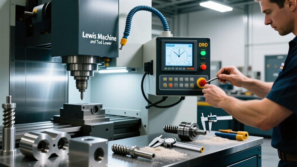
| 500 Hours | Control Pendant | Clean membrane switches; inspect E-Stop relay wiring for vibration loosening. | Contact cleaner, thermal camera for hotspots. |
| Annual | Full Axis System | Laser interferometry calibration to map backlash and pitch error across travel. | Renishaw XL-80 or API Radian. |
Troubleshooting Axis Drift in Mag Well Milling
When performing secondary milling on the mag well of a Lewis Machine and Tool lower, operators occasionally report "ghost movements" or axis drift on the DRO display, where the readout changes without the table moving. This is rarely a mechanical failure and almost always an electrical interference issue.
Y-Axis Drift Diagnostic Flow
- Isolate the VFD Interference: Variable Frequency Drives (VFDs) on coolant pumps and spindle motors generate high-frequency electromagnetic interference (EMI). Action: Turn off the coolant pump. If the DRO stops drifting, you have a grounding loop issue.
- Check Shield Grounding: DRO encoder cables must be shielded, and the shield must be grounded at one end only (usually the DRO head unit). Action: Use a multimeter to check for continuity between the cable shield and the machine chassis at both ends. If continuous at both ends, cut the ground wire at the read-head side to break the loop.
- Inspect the Scale Gap (Magnetic Systems): For Newall Spherosyn scales, the read head must maintain a precise gap (typically 0.010" to 0.030"). Action: If the machine experienced a crash or heavy vibration, the read head bracket may have shifted. Use a feeler gauge to verify the gap. A gap exceeding 0.040" will cause signal dropouts that the DRO interprets as rapid axis movement.
- Verify Linear Bearing Preload: If the DRO is accurate but the part is out of tolerance, the issue is mechanical stick-slip. Action: Check the gib adjustments and way lube flow. Insufficient way lube causes the table to jump in 0.001" increments, which the DRO will accurately display, but the operator cannot manually jog smoothly.
Environmental Controls and Calibration Economics
The environment in which the Lewis Machine and Tool lower is inspected and finished plays a massive role in control system longevity. Aluminum fines are conductive. If they accumulate inside the DRO display unit or the CNC control pendant, they can bridge circuit board traces, causing short circuits or erratic screen behavior.
"In defense manufacturing, the cost of scrapping a batch of ambi-lowers due to an uncalibrated DRO far exceeds the cost of an annual service contract. We mandate positive-pressure air purges on all manual inspection station encoders to keep aluminum dust out of the read heads."
— Lead Metrology Engineer, Tier 1 Defense Contractor
2026 Service and Calibration Costs
Budgeting for control system maintenance is critical for shop floor profitability. Based on current industrial service rates, here is what machine shops should expect to pay for professional DRO and encoder maintenance:
- On-Site Laser Calibration (Per Axis): $450 – $650. This includes pitch error compensation mapping and backlash adjustment.
- Complete DRO Replacement (3-Axis Newall System): $2,800 – $3,500 (hardware and installation). Upgrading from optical to magnetic encoders is highly recommended for shops dedicated to aluminum lower receiver production.
- Control Pendant Rebuild (Membrane & PCB): $1,200 – $1,800. Necessary when coolant ingress causes membrane switch delamination or PCB corrosion.
For further technical documentation on encoder installation and environmental protection, shops should consult the Newall Measurement Systems Support portal, as well as the Heidenhain Service archives for optical scale care. Maintaining the integrity of your DRO and control feedback loops is not just a matter of machine upkeep; it is the foundational requirement for delivering the uncompromising reliability that the Lewis Machine and Tool lower platform is known for.