How Machine Tool Coolant Recycling Affects Rigidity and Vibration
Discover how integrated machine tool coolant recycling systems impact CNC rigidity. Learn modal analysis techniques and vibration damping strategies.
The Hidden Dynamic Costs of Integrated Coolant Recycling
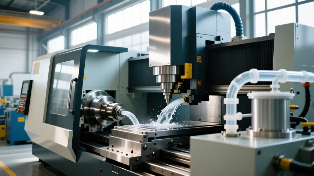
In the push for sustainable manufacturing and zero-liquid-discharge facilities, the integration of high-capacity machine tool coolant recycling systems directly onto CNC enclosures has become a dominant trend. Modern setups frequently utilize centrifugal separators, vacuum drum filters, and high-pressure delivery pumps (often exceeding 1,000 PSI) mounted to the machine base or column to minimize floor space. While this saves real estate, it introduces a severe, often overlooked engineering challenge: forced harmonic vibration that compromises machine tool rigidity.
When a 15-HP centrifugal recycling motor operates at 3,500 RPM, it generates a forcing frequency of approximately 58.3 Hz. If the structural bending mode of the machine’s Y-axis column falls within the 50–70 Hz range—common in mid-sized vertical machining centers (VMCs)—resonance occurs. This structural coupling can amplify tool tip deflection by up to 40 microns, destroying surface finishes and accelerating insert wear during finishing passes.
⚠️ The 58 Hz Resonance Trap: Standard 4-pole AC motors used in coolant recycling pumps operate near 3,600 RPM (60 Hz). Because most VMC columns exhibit their first major lateral bending mode between 55 Hz and 75 Hz, hard-mounting these recycling units directly to the cast iron base creates a near-guaranteed resonance conflict during heavy roughing operations.Modal Analysis: Testing Rigidity with Active Coolant Systems
Traditional machine tool rigidity testing involves impact hammer tests (bump tests) with the machine powered down. However, according to research highlighted by the Society of Manufacturing Engineers (SME), static modal analysis fails to capture the dynamic stiffness degradation caused by auxiliary rotating mass. To accurately map the machine's Frequency Response Function (FRF) in a 2026 production environment, testing must occur with the machine tool coolant recycling system fully operational.
Step-by-Step Impact Testing Protocol
- Sensor Placement: Mount PCB Piezotronics ICP accelerometers (e.g., Model 352C33) at the spindle nose, the Y-axis column midpoint, and the coolant recycling pump housing.
- Baseline FRF Capture: Strike the spindle housing with an instrumented modal hammer (e.g., Kistler 9722A) while the recycling system is powered off. Record the baseline natural frequencies and damping ratios.
- Active FRF Capture: Power on the coolant recycling system and high-pressure pumps. Repeat the impact test.
- Compare Damping Ratios: Analyze the shift in the FRF peaks. An active, hard-mounted pump will typically show a 15% to 30% reduction in the damping ratio (ζ) at the column's primary bending mode due to the continuous injection of vibrational energy.
Vibration Amplitude & Tool Tip Deflection Matrix
The following data illustrates the difference in tool tip compliance when a 15-HP coolant recycling centrifuge is hard-mounted versus dynamically isolated on a 40,000-lb VMC base.
| Mounting Configuration | Pump Forcing Frequency | Column Vibration Amplitude | Tool Tip Deflection (Dynamic) | Chatter Risk Level |
|---|---|---|---|---|
| Hard-Mounted (Steel Bolts) | 58.3 Hz | 12.4 µm RMS | 38.5 µm peak-to-peak | Critical (Severe Chatter) |
| Elastomeric Pads (70 Durometer) | 58.3 Hz | 4.1 µm RMS | 14.2 µm peak-to-peak | Moderate |
| Tuned Mass Damper + VFD Detuned (51 Hz) | 51.6 Hz | 1.2 µm RMS | 3.8 µm peak-to-peak | Negligible |
Engineering Solutions for Vibration Decoupling
Mitigating the vibration introduced by machine tool coolant recycling systems requires a multi-tiered approach addressing both structure-borne noise and fluid-induced pulsation. Data from the NIST Manufacturing Engineering Laboratories emphasizes that addressing the source path is vastly more cost-effective than attempting to stiffen the machine column after the fact.
1. Elastomeric and Composite Isolation Mounts
Never bolt recycling pump bases directly to the machine enclosure or base. Instead, utilize composite isolation pads. Fabreeka International’s composite pads, rated at 70 to 80 durometer, provide optimal high-frequency isolation for rotating equipment. For pumps generating low-frequency shaking forces (below 20 Hz), use spring isolators with neoprene cup mounts, such as the Mason Industries ND style, ensuring the static deflection of the spring is at least five times greater than the dynamic deflection caused by the pump's operating frequency.
2. Variable Frequency Drive (VFD) Detuning
If modal analysis reveals that your coolant recycling pump's operating frequency perfectly aligns with a structural weak point, use a VFD to shift the motor speed. Dropping the centrifuge motor from 3,500 RPM (58.3 Hz) to 3,100 RPM (51.6 Hz) moves the forcing frequency out of the critical 55-65 Hz column resonance band. This slight reduction in RPM typically results in a negligible drop in coolant throughput but yields a massive improvement in dynamic rigidity.
3. Flexible Piping and Fluid Pulsation Dampeners
High-pressure coolant delivery systems integrated with recycling units generate severe fluid pulsations. These pressure waves travel through rigid steel piping and excite the machine structure. Install flexible stainless steel braided bellows at every pipe junction between the recycling unit and the machine base. Additionally, integrate inline hydraulic pulsation dampeners (accumulators) charged with nitrogen to 60% of the maximum system pressure to absorb the pressure spikes generated by piston-style high-pressure pumps.
"In high-speed aerospace milling, we found that 30% of unexplained chatter marks during finishing passes were traced back to the vacuum filtration motors on the coolant recycling unit. Decoupling the auxiliary systems from the machine base is no longer optional for sub-5-micron tolerance work." — Lead Manufacturing Engineer, Tier 1 Aerospace Supplier.
Thermal Rigidity: The Coolant Temperature Factor
While dynamic vibration is a primary concern, machine tool coolant recycling systems also dictate thermal rigidity. Advanced recycling systems incorporate chillers to maintain coolant at a strict 20°C (±0.5°C). If the recycling chiller fails or is undersized, the coolant temperature rises, transferring heat into the machine's cast iron base and linear guideways. According to Sandvik Coromant's machining fundamentals, thermal growth in the Y-axis can alter the preload on linear roller bearings. An increase in preload artificially stiffens the axis but drastically increases friction and the risk of stick-slip vibration (the Stribeck effect), while a loss of preload destroys rigidity entirely. Ensuring your recycling system's thermal management loop is functioning perfectly is just as critical as mechanical vibration isolation.
Real-World Troubleshooting Matrix
Use this decision matrix to diagnose chatter and vibration issues suspected to be linked to your coolant infrastructure.
| Symptom Observed | Probable Coolant System Cause | Corrective Action |
|---|---|---|
| Consistent chatter marks at specific spindle speeds, worsening when coolant pump turns on. | Structural resonance coupling between pump motor frequency and machine column bending mode. | Install composite isolation pads under pump; detune pump RPM via VFD by 10-15%. |
| Intermittent surface finish degradation; high-frequency "buzzing" sound from the spindle area. | Fluid pulsation from high-pressure pump traveling through rigid piping to the spindle union. | Install flexible braided bellows on all coolant lines; add inline nitrogen-charged accumulators. |
| Dimensional drift over a 4-hour shift; stick-slip vibration during slow Y-axis contouring. | Coolant recycling chiller failure causing thermal expansion and altered linear guideway preload. | Service chiller heat exchanger; verify coolant temperature stability at ±0.5°C; re-lube guideways. |
| Tool tip deflection spikes only during heavy roughing when conveyor and centrifuge run simultaneously. | Low-frequency shaking forces from the chip conveyor transferring through the shared machine base. | Isolate conveyor drive motor; ensure conveyor frame is not physically contacting the VMC enclosure. |
Summary of Best Practices for 2026 Machine Integration
As machine tool coolant recycling systems become more powerful and deeply integrated into the CNC footprint, treating them as isolated auxiliary equipment is a critical error. Manufacturing engineers must include active coolant systems in their modal analysis protocols. By utilizing elastomeric isolation mounts, implementing VFD detuning strategies, and managing fluid pulsations with flexible plumbing, shops can maintain the structural rigidity required for high-precision, high-speed machining without sacrificing the environmental and economic benefits of advanced coolant recycling.