Mastering Machine Tools AI for Predictive Calibration Standards
Learn how operators use machine tools AI to maintain ISO 230 accuracy standards, reduce downtime, and master predictive calibration best practices.
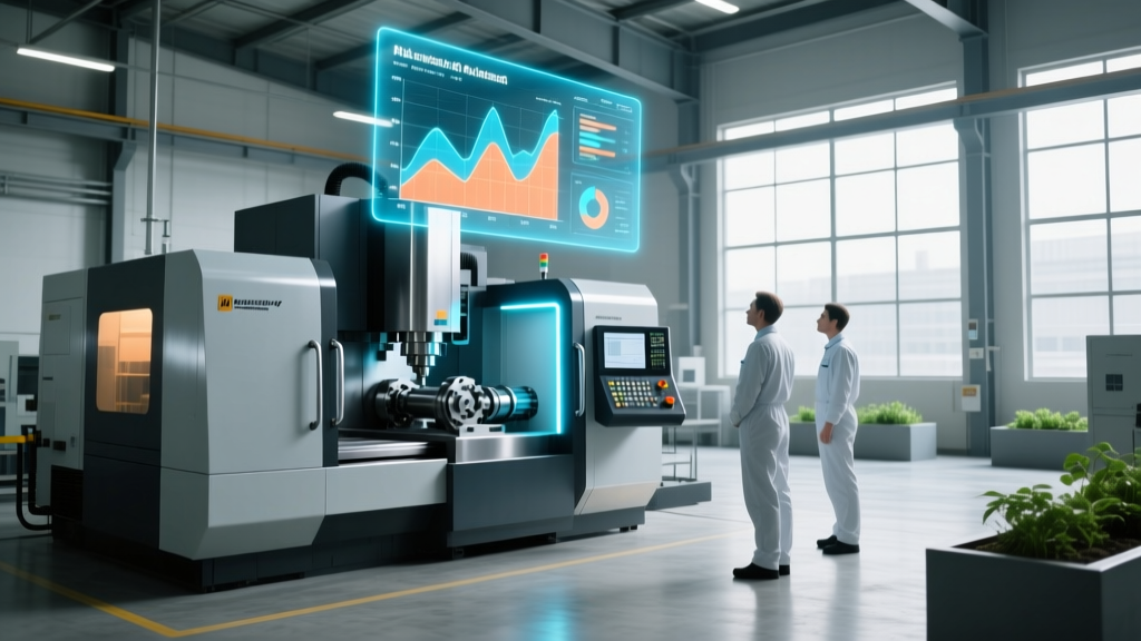
The integration of machine tools AI into CNC architectures has fundamentally altered how machine shops approach accuracy standards and calibration. Historically, maintaining geometric and volumetric accuracy required scheduling annual or semi-annual downtime for manual laser interferometry and ballbar testing. Today, AI-driven edge computing and continuous sensor feedback loops allow operators to transition from reactive calibration to predictive accuracy management.
For modern machine shop operators and setup technicians, mastering these AI systems is no longer optional. It is a critical competency required to maintain compliance with stringent international accuracy standards while maximizing spindle uptime. This guide details the operational best practices for leveraging AI calibration tools to meet and exceed ISO and ASME tolerances.
⚠️ CRITICAL WARNING: Never blindly trust AI-generated volumetric compensation maps without periodic physical baseline verification. AI models can drift if external factors—such as foundation settling or undetected linear scale contamination—introduce non-linear errors that fall outside the algorithm's training parameters.Core Accuracy Standards in the AI Era
Operators must understand the specific standards that AI calibration systems are programmed to optimize. The algorithms embedded in modern controls like the Siemens SINUMERIK ONE or Heidenhain TNC7 are explicitly designed to minimize deviations defined by these frameworks:
- ISO 230-2 (Linear Axes Positioning): Defines the accuracy and repeatability of linear axes. AI systems continuously monitor encoder feedback against commanded positions to predict and compensate for backlash and pitch errors before they exceed the ISO 230-2 thresholds.
- ISO 230-3 (Thermal Effects): Governs the measurement of thermal growth. Machine tools AI excels here by correlating spindle load, coolant temperature, and ambient shop temperature to predict Z-axis drop and X/Y-axis skew in real-time.
- ASME B5.54 (Volumetric Performance): Evaluates the 3D volumetric accuracy of 5-axis machines. AI kinematic models continuously update rotary axis pivot points based on real-time torque and temperature sensor data.
For a comprehensive review of the latest linear axis testing codes, operators should reference the ISO 230-2:2023 standard documentation, which outlines the updated statistical methods for determining positioning accuracy.
Traditional vs. AI-Assisted Calibration Metrics
Understanding the ROI and operational shift requires comparing legacy methods with modern AI implementations. The following matrix highlights the operational differences for a standard 3-axis VMC (e.g., Haas VF-2 or DMG MORI CMX V).
| Parameter | Traditional Schedule-Based | AI-Driven Predictive |
|---|---|---|
| Downtime per Calibration Event | 4 to 8 hours per axis | 15 minutes (Automated warm-up cycle) |
| Volumetric Error Compensation | Static grid (updated annually) | Dynamic, real-time kinematic updates |
| Thermal Drift Handling | Manual warm-up routines | Continuous AI thermal modeling |
| Operator Skill Requirement | Specialized metrology technician | CNC operator with AI dashboard training |
| Estimated Annual Downtime Cost | $8,000 - $12,000 per machine | $1,500 (Sensor maintenance only) |
Operator Training Protocol: Interfacing with Machine Tools AI
Training operators to use AI calibration interfaces requires a structured, three-phase approach. This protocol ensures the AI model is fed accurate baseline data and that operators know how to interpret the resulting analytics.
Phase 1: Physical Baseline Verification
Before enabling AI continuous compensation, the machine's physical baseline must be verified using high-precision metrology. Operators should use a wireless ballbar system, such as the Renishaw QC20-W or XL-80 laser interferometer, to establish the ground truth.
- Clean all linear guideways and way covers to remove tramp oil and swarf.
- Execute a standardized 30-minute spindle and axis warm-up cycle.
- Run the ballbar test at three distinct feed rates (e.g., 1000, 2000, and 4000 mm/min) to capture servo lag and stick-slip friction data.
- Upload the raw ISO 230-4 circular test data into the CNC control's AI training module to establish the initial kinematic map.
Phase 2: AI Dashboard Monitoring and Interpretation
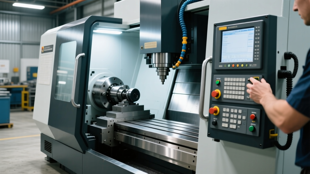
Modern CNC controls feature dedicated AI diagnostic screens. Operators must be trained to distinguish between normal thermal settling and abnormal mechanical degradation.
- RMS Error vs. Peak Error: Train operators to monitor the Root Mean Square (RMS) positioning error. A sudden spike in Peak Error while RMS remains stable usually indicates a localized obstruction (e.g., a chip jammed in the way cover), not a systemic calibration failure.
- Thermal Compensation Vectors: Operators should verify that the AI's Z-axis thermal compensation vector correlates with the spindle load meter. If the spindle is idle but the AI is applying heavy Z-axis compensation, the ambient temperature sensors may be compromised by direct sunlight or a nearby open bay door.
Phase 3: Executing Micro-Compensations
When the AI flags a predicted tolerance drift (e.g., predicting a 12-micron Y-axis shift over the next 4 hours of machining), operators must know how to intervene safely. Instead of overriding the AI, operators should trigger an automated 'micro-calibration' cycle. This involves the machine probing a fixed, thermally stable master artifact (like a calibrated 3D sphere) mounted in the tool magazine or table corner, allowing the AI to update its compensation map in under 45 seconds.
Real-World Edge Case: Thermal Growth in 5-Axis Trunnions
One of the most common failure modes in 5-axis machining is thermal growth in the trunnion table's rotary axes (A and C axes). As the direct-drive torque motors heat up, the physical center of rotation shifts.
In a recent aerospace titanium milling application, a shop experienced a 22-micron Z-axis drop and an 8-micron X-axis shift after 3 hours of continuous 5-axis contouring. By integrating machine tools AI that monitored the torque motor current and stator temperature, the control successfully predicted this exact kinematic shift and applied inverse offsets in real-time, holding the final part within a strict 15-micron true position tolerance.
Operators must be trained to ensure the trunnion's internal cooling circuits are flowing at the correct pressure (typically 2.5 to 3.0 bar). If coolant flow drops, the AI model will quickly max out its compensation limits, resulting in a control alarm.
Troubleshooting AI Calibration False Positives
AI systems are highly sensitive. Operators frequently encounter 'false positive' calibration alarms where the AI predicts an out-of-tolerance condition, but physical part inspection proves the machine is accurate. Use this decision tree to troubleshoot:
- Check Linear Scale Contamination: Open the axis way covers. If coolant or fine graphite dust has bypassed the wipers and settled on the glass or steel linear scale, the AI will read micro-vibrations as positioning errors. Clean with isopropyl alcohol and a lint-free wipe.
- Verify Master Tool Setter Calibration: If the AI relies on a tool-setting laser (e.g., Renishaw NC4) to update tool length offsets dynamically, a dirty laser lens will cause the AI to apply erroneous Z-axis compensation. Clean the lens and run the laser's internal calibration routine.
- Analyze Foundation Vibration: AI accelerometers can mistake external shop floor vibrations (from a nearby stamping press or forklift traffic) for axis servo instability. Review the AI's frequency domain analysis; if the error spikes correlate with external low-frequency vibrations, adjust the AI's filtering threshold to ignore sub-5Hz noise.
Summary of Best Practices
Mastering machine tools AI for calibration requires a shift in mindset. Operators must stop viewing calibration as a mechanical adjustment task and start treating it as a data validation process. By maintaining pristine sensor environments, understanding the underlying ISO standards, and knowing how to troubleshoot AI data anomalies, shops can leverage predictive calibration to achieve unprecedented levels of accuracy and uptime.