Safety Compliance: Barcode Scanning Machine Vision Integration Tools
Learn how to integrate barcode scanning machine vision tools into smart CNCs while maintaining ISO 13849 and IEC 62443 safety compliance.
The Intersection of Vision Systems and ISO 13849 in Smart Machine Tools
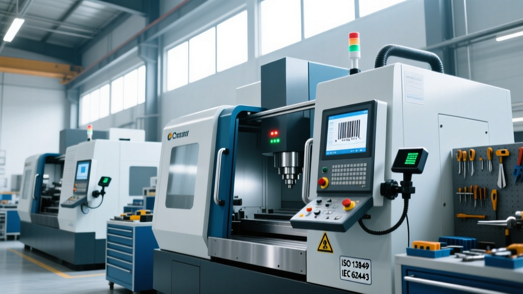
As machine shops transition to Industry 4.0 connectivity, automated tool identification and part tracking have become mandatory for high-mix, low-volume production. However, deploying barcode scanning machine vision integration tools introduces complex safety liabilities. When a vision system verifies that the correct cutting tool is loaded before allowing a CNC spindle to start, that camera and scanner transition from a mere data-collection device to a Safety-Related Part of a Control System (SRP/CS). Under ISO 13849-1:2023, any component that initiates, transmits, or executes a safety command must meet specific Performance Levels (PL), typically PL d or PL e for machine tool interlocks.
Standard barcode readers output discrete 24V DC signals to a Programmable Logic Controller (PLC). If the scanner misreads a degraded Datamatrix code due to coolant smearing and incorrectly outputs a 'Tool Verified' signal, the machine may execute a catastrophic crash. Therefore, the integration architecture must include diagnostic coverage, such as cross-monitoring or safe-protocol communication, to detect sensor faults and force a safe state (Category 3 or 4 architecture).
Warning: Never route standard 2D barcode reader discrete outputs directly into a standard PLC input for hardwired safety interlocking. Standard inputs lack the diagnostic coverage required for PL d. You must utilize safety-rated gateways or PROFIsafe/CIP Safety network protocols to integrate vision data into the safety PLC.Hardware Matrix: Safety-Rated Vision and Scanning Systems
Selecting the correct hardware is the first step in compliance. Industrial vision tools must withstand harsh machine shop environments (IP67/IP69K ratings) while supporting safety-over-Ethernet protocols. Below is a comparison of three industry-standard barcode scanning machine vision integration tools optimized for safety-critical CNC environments.
| Model | Est. Price (2026) | Safety Protocol Support | Ideal Machine Tool Application |
|---|---|---|---|
| Cognex In-Sight 2800 | $3,800 - $4,500 | CIP Safety, PROFINET PROFIsafe | Automated tool magazine verification on 5-axis mills |
| Keyence SR-1000W | $1,900 - $2,400 | EtherCAT Safety, EtherNet/IP | Raw material billet tracking and fixture clamping interlocks |
| SICK ICR890 (with flexiSoft) | $5,200 - $6,800 | EFI-pro, Safe Controller Integration | High-speed lathe part-ejection verification and door interlocks |
IEC 62443: Securing the Vision Network Endpoint
Safety in Industry 4.0 extends beyond physical machine guarding to cybersecurity. According to the NIST SP 800-82 Guide to Industrial Control Systems Security, vision systems and barcode scanners are frequently overlooked IoT endpoints. If a malicious actor or rogue malware compromises a vision system on the shop floor, they can inject false barcode data into the Manufacturing Execution System (MES) or bypass safety interlocks by spoofing 'all-clear' signals.
Mandatory Network Segmentation Strategies
- VLAN Isolation: Barcode scanners and vision cameras must reside on a dedicated VLAN (Virtual Local Area Network) separate from the enterprise IT network and standard HMI traffic.
- Port Security: Enable 802.1X port-based network access control on the industrial switch connecting the vision tools. This prevents unauthorized devices from being plugged into the camera's Ethernet drop.
- Disable Unused Services: Out-of-the-box industrial cameras often have FTP, Telnet, and HTTP services enabled for easy debugging. These must be disabled via the manufacturer's configuration software, leaving only the specific EtherNet/IP or PROFINET ports open.
Optical FMEA: Failure Modes in Machine Tool Environments
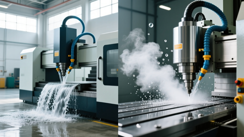
A Failure Mode and Effects Analysis (FMEA) specific to the optical environment is required for safety validation. Machine tools present unique challenges that degrade barcode readability and machine vision accuracy, potentially leading to unsafe machine states if the system defaults to an 'open' (unsafe) condition upon read-failure.
Expert Insight: 'The most common cause of safety-interlock bypass in vision-guided CNCs is specular reflection from cutting fluid. When coolant pools on a shiny carbide tool shank, it acts as a convex mirror, blinding the camera sensor and causing the system to misinterpret the tool ID.' — Lead Automation Engineer, Tier 1 Aerospace Machine ShopMitigation Tactics for Optical Failures
- Polarized Lighting: Do not rely on the camera's built-in LED ring light. Install external 24V DC dome lights equipped with linear polarizing filters (e.g., MidOpt BP470 bandpass filters) to eliminate coolant glare and isolate the specific wavelength of the LED illumination.
- Direct Part Marking (DPM) Validation: For metal-stamped or laser-etched barcodes on toolholders, ensure the vision tool supports DPM algorithms. Standard 1D/2D algorithms will fail on low-contrast dot-peened marks, causing unnecessary machine stops and tempting operators to bypass the safety interlock.
- Air Purge Systems: Integrate a localized air-knife or purge tube directed at the camera lens and barcode window. Connect this to the machine's M-code (e.g., M8/M9 coolant toggle) so the lens is blasted with clean, dry air immediately before the scan cycle initiates.
Step-by-Step Safety Validation Protocol
Before releasing a machine tool with integrated vision interlocks to production, the following validation protocol must be executed and documented to satisfy OSHA machine guarding requirements and internal ISO 13849 compliance audits.
- Inject Fault Conditions: Physically obstruct the camera lens with 50%, 75%, and 100% opacity filters. Verify that the safety PLC detects the loss of diagnostic heartbeat and transitions the machine to a Safe Torque Off (STO) state within the calculated response time (typically < 50ms).
- Simulate Network Latency: Use a network packet generator to introduce 500ms+ latency and packet loss on the PROFINet/EtherNet/IP segment. The safety gateway must interpret this as a communication fault and trigger the interlock.
- Test Swarf and Coolant Interference: Apply a heavy coat of the specific cutting fluid and aluminum/titanium swarf used in production to the barcode target. The system must either successfully read the code (if using polarized lighting) or safely fault out. It must never return a false-positive match for a different tool ID.
- Verify Bypass Prevention: Attempt to manually force the PLC boolean tag for 'Tool_Verified' via the HMI while in Auto mode. The safety PLC logic must reject manual overrides of safety-critical vision tags.
Compliance Documentation and Traceability
Maintaining compliance requires rigorous documentation. Every barcode scanning machine vision integration tool deployed as a safety interlock must have a corresponding safety dossier. This dossier must include the SISTEMA calculation files proving the PL rating, the optical FMEA report, network topology diagrams proving IEC 62443 segmentation, and the signed validation protocol. As machine tools become increasingly autonomous, treating vision systems with the same rigorous safety engineering as physical light curtains and e-stop circuits is non-negotiable for modern manufacturing compliance.