Milling Machine Tool Holders: Tapers, Grip Force & Runout Specs
Explore the technical specifications of milling machine tool holders. Learn how CAT, BT, and HSK tapers work, grip force metrics, and runout limits.
The Physics of the Spindle Interface
The interface between the machine spindle and the cutting tool dictates dimensional accuracy, surface finish, and tool life. Milling machine tool holders are not passive adapters; they are precision-engineered clamping and dampening systems. Understanding their technical specifications—from taper geometry to radial clamping force—is mandatory for optimizing metal removal rates (MRR) and preventing catastrophic tool failure in modern CNC environments.
At the core of this interface is the taper. The standard V-flange taper utilized by CAT and BT holders relies on a 7:24 ratio (3.5 inches of diameter change per 12 inches of length). This steep angle ensures the tool holder releases easily when the drawbar retracts. However, at high centrifugal forces (typically above 10,000 RPM), the spindle nose expands radially. Because the solid tool holder shank does not expand at the same rate, the 7:24 taper loses axial contact, pulling upward into the spindle and altering the Z-axis tool length offset.
Taper Standards Decoded: CAT vs. BT vs. HSK
Selecting the correct taper standard requires understanding the mechanical limitations of each geometry. While CAT and BT dominate legacy and mid-range vertical machining centers (VMCs), HSK has become the standard for high-speed, 5-axis simultaneous machining.
| Specification | CAT40 (V-Flange) | BT40 (MAS 403) | HSK-A63 (DIN 69893) |
|---|---|---|---|
| Taper Ratio | 7:24 (Single Contact) | 7:24 (Single Contact) | 1:10 (Dual Contact) |
| Flange Design | Asymmetrical (V-groove) | Symmetrical | Hollow Shank, Face/Taper |
| Pull-Stud Thread | 5/8'-11 UNC (Typical) | M16 x 2.0 | Internal Expander / Clamping |
| Max Recommended RPM | 12,000 RPM | 12,000 RPM | 24,000+ RPM |
| Axial Rigidity | Moderate | Moderate | Extreme (Face Contact) |
The HSK system solves the high-speed expansion problem through dual-contact mechanics. The 1:10 taper is shallower, and the hollow shank design allows the tool holder face and the spindle face to clamp together simultaneously. According to Sandvik Coromant, this face-and-taper contact provides up to four times the axial rigidity of a standard 7:24 taper, eliminating Z-axis growth at high RPMs.
Clamping Mechanisms & Grip Force Metrics
The method by which the cutting tool is secured inside the holder directly impacts vibration dampening and tool life. As of 2026, shops primarily choose between ER collets, hydraulic chucks, and shrink-fit systems.
ER Collet Systems (DIN 6499)
ER collets are the most versatile but offer the lowest grip force. An ER32 collet, when tightened with a standard nut torque of 80–100 ft-lbs, generates approximately 10 kN (2,248 lbs) of axial clamping force. The slotted design of the collet allows for a collapse range of about 0.040 inches, making it ideal for holding various shank diameters. However, the slots introduce inherent asymmetry, which limits high-speed balance.
Hydraulic Tool Holders
Hydraulic holders utilize an internal oil bladder. Turning a setscrew pressurizes the hydraulic fluid to roughly 25,000 psi, causing a thick steel sleeve to expand and grip the tool shank uniformly. This provides exceptional vibration dampening, making hydraulic holders ideal for finishing operations in hardened steels and titanium. A premium HSK-A63 hydraulic holder averages $450–$650 in current market pricing, but the extension of end mill life often justifies the capital expenditure.
Shrink-Fit Technology
Shrink-fit holders rely on thermal expansion. The holder is heated via an induction coil to 400°C–450°C (750°F–840°F), expanding the bore. The carbide shank is inserted, and as the steel cools to room temperature, it contracts, generating up to 15,000 N (3,372 lbs) of uniform radial retention force. As detailed in technical literature from Modern Machine Shop, shrink-fit holders offer the lowest profile and highest rigidity, making them the undisputed choice for deep-cavity milling and 5-axis contouring where clearance is critical.
Technical Callout: Balancing StandardsFor operations exceeding 10,000 RPM, tool holders must be balanced to ISO 1940-1 G2.5 standards. A standard CAT40 holder unbalanced might vibrate at 0.0008 inches at 12,000 RPM, whereas a G2.5 balanced holder restricts vibration to less than 0.0001 inches, preventing premature spindle bearing wear.
Runout Tolerances and Machining Accuracy
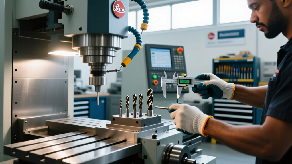
Total Indicator Runout (TIR) is the measure of how much the cutting tool deviates from the true centerline of rotation. Runout is typically measured at 3x the tool diameter (3xD) from the collet nut or holder face.
- Standard ER Holders: 0.0005 inches to 0.0008 inches TIR at 3xD. Acceptable for roughing and general-purpose drilling.
- Precision ER Holders (e.g., Rego-Fix, Haimer): Guaranteed < 0.00012 inches (3 microns) TIR at 3xD. Required for high-speed finishing and micro-end mills.
- Shrink-Fit Holders: < 0.0001 inches (2.5 microns) TIR. The uniform thermal contraction ensures the tool shank is perfectly centered.
- Milling Chucks (Side-lock / Weldon): 0.001 inches to 0.002 inches TIR. The set-screw pushes the tool off-center; these should only be used for heavy roughing where runout is secondary to pull-out prevention.
Excessive runout causes uneven chip loads. In a 4-flute end mill, a TIR of just 0.0005 inches can cause one flute to take 70% of the cutting load while the opposite flute rubs, reducing tool life by up to 50% and degrading surface finish.
Failure Modes: Bell-Mouthing and Fretting Corrosion
Even high-end tool holders fail if maintenance protocols are ignored. The two most common mechanical failure modes in milling operations are bell-mouthing and fretting corrosion.
Bell-Mouthing
Bell-mouthing occurs when the large end of the spindle taper wears unevenly, creating a bell-shaped deformation. This is caused by heavy radial cutting forces (such as aggressive side-milling with long-reach end mills) that act as a lever, prying the tool holder against the front lip of the spindle. Over time, this compromises the 7:24 contact area, leading to chatter and lost pull-stud retention. Regular spindle qualification using a test arbor and dial indicator is required to detect bell-mouthing before it scraps parts.
Fretting Corrosion
Fretting corrosion appears as a copper-colored or rust-like pitting on the tool holder taper. It is caused by micro-vibrations between the holder and the spindle during heavy cutting, which breaks down the oil film and causes micro-welding of the steel surfaces. If left untreated, the tool holder will seize inside the spindle. To prevent this, operators must clean tapers with isopropyl alcohol and apply a microscopic layer of specialized spindle oil (never grease or heavy way oil, which attracts abrasive swarf) before insertion.
Selection Framework: Matching the Holder to the Operation
Choosing the correct milling machine tool holder requires matching the clamping technology to the specific machining operation. Use the following decision framework to optimize your tool crib:
- Heavy Roughing (High MRR, Interrupted Cuts): Use Milling Chucks or Weldon Side-Lock holders. The mechanical set-screw or high-torque clamping mechanism prevents the tool from being pulled out of the holder during aggressive radial engagements.
- Semi-Finishing and General Milling: Use Precision ER Collet Chucks. They offer a balance of grip force, versatility, and acceptable runout for standard 2D and 3D contouring.
- High-Speed Finishing & Hard Milling: Use Hydraulic Holders. The internal fluid bladder absorbs high-frequency vibrations, protecting the cutting edges of solid carbide ball nose end mills and leaving superior surface finishes on mold steels.
- 5-Axis Simultaneous & Deep Cavity Work: Use Shrink-Fit Holders. The slim profile prevents collisions with complex part geometries, and the extreme rigidity maintains tight tolerances on deep-reach features.
For further reading on optimizing tool holding strategies for advanced alloys, refer to the metalworking knowledge base provided by Kennametal. Properly specifying and maintaining your tool holders is not a secondary concern; it is the foundational requirement for precision milling.