Mill Machine Tools Setup and Operator Training Best Practices
Master mill machine tools setup, speeds, feeds, and safety. This operator training guide covers toolholding, touch-offs, and troubleshooting.
Operator proficiency with mill machine tools dictates the boundary between profitable production and catastrophic spindle failure. Improper tool setup, incorrect speeds and feeds, and inadequate toolholding account for over 40% of scrapped parts and unplanned downtime in both manual and CNC milling environments. This training guide provides actionable, shop-floor protocols for tool selection, setup, and operation.
⚠️ Safety Directive: Before operating any mill machine tools, verify that all machine guards are in place and interlocks are functional. Refer to the OSHA Machine Guarding Standards to ensure compliance with point-of-operation guarding, specifically for rotating spindles and flying chip hazards. Never wear gloves while operating manual milling machines.Toolholding and Collet Selection Protocols
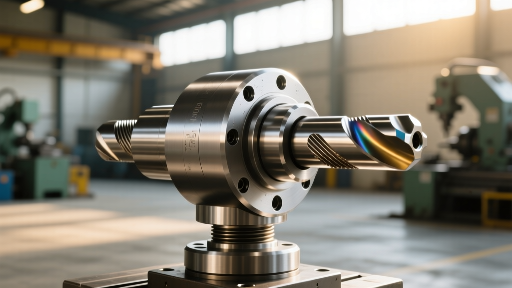
The connection between the spindle and the cutting tool is the most critical mechanical interface on the machine. Selecting the wrong toolholder compromises rigidity and introduces runout.
Retention Knobs (Pull Studs)
For V-flange tooling (CAT40, BT40), never use standard 8620 carbon steel retention knobs. Operators must upgrade to 4340 alloy steel pull studs heat-treated to 45-50 HRC, rated for a minimum of 2,500 lbs of pull force. A failed pull stud under high radial loads will result in the toolholder ejecting from the spindle taper at high velocity.
Collet Clamping Ranges
ER collets are standard for end mills under 3/4" diameter, but operators frequently misuse their clamping ranges. An ER32 collet has a maximum collapse range of 1mm (0.040"). Rule: Never use an ER32 collet designed for a 1/2" (12.7mm) shank to hold a 0.490" shank tool. For heavy roughing in steel where torque exceeds 150 Nm, abandon ER collets entirely and use Weldon shank (side-lock) holders or TG100 collets to prevent tool pull-out.
Step-by-Step Tool Touch-Off Procedure
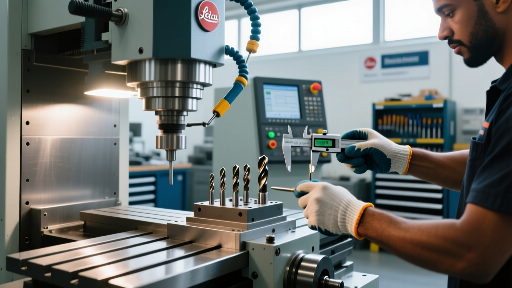
Accurate work coordinate system (WCS) setup requires a repeatable touch-off process. Follow this exact sequence for manual and CNC mills:
- Taper Cleaning: Wipe the spindle taper and toolholder taper with a lint-free shop towel dampened with isopropyl alcohol. A single 0.001" chip on the taper introduces 0.003" of runout at the tool tip.
- Tool Seating: Insert the toolholder and engage the drawbar or automatic tool changer (ATC). For manual Bridgeport-style mills, tighten the R8 drawbar until snug, then apply exactly one-half turn with a wrench. Over-tightening swells the collet and ruins the threads.
- Z-Axis Touch-Off: Use a high-quality electronic tool setter (e.g., Haimer 3D Sensor) or a standard 0.200" diameter edge finder. If using a manual edge finder, approach the workpiece at 50% rapid override to prevent shattering the spring-loaded tip.
- Backlash Compensation: Always approach the final touch-off position in the negative direction (moving down or left) to eliminate ballscrew backlash from your coordinate calculation.
Speeds, Feeds, and Chip Load Matrix
Relying on "feel" or outdated machinist manuals leads to premature tool wear. Modern carbide end mills with advanced coatings require specific parameters. The table below provides baseline starting parameters for a standard 1/2" diameter, 4-flute solid carbide end mill. For exact calculations based on specific tool geometries, consult the Harvey Tool Technical Guides.
| Material | Tool Coating | Spindle Speed (RPM) | Feed Rate (IPM) | Chip Load (IPT) | Coolant Strategy |
|---|---|---|---|---|---|
| 6061-T6 Aluminum | ZrN (Unpolished) | 12,000 | 144 | 0.003" | Flood (8-10% conc.) |
| 1018 Cold Rolled Steel | TiAlN | 3,500 | 42 | 0.003" | Flood or MQL |
| 304 Stainless Steel | AlCrN | 1,800 | 14.4 | 0.002" | High-Pressure Flood |
| TI-6AL-4V Titanium | AlTiN | 900 | 5.4 | 0.0015" | High-Pressure Flood |
The parameters above assume a full slot (100% radial engagement). When performing adaptive clearing or trochoidal milling with a 5% to 10% radial stepover, you must increase the spindle speed by 20-30% and the feed rate by 50-100% to maintain proper chip thickness and prevent work hardening, especially in stainless steel and titanium.
Coolant Delivery and Concentration Management
Coolant is not just for temperature control; it is a vital chip evacuation and lubrication medium. Operators must verify coolant concentration daily using a refractometer.
- Aluminum Machining: Maintain a concentration of 8-10% using a semi-synthetic fluid (e.g., TRIM MicroSol 685). Concentrations below 7% will cause built-up edge (BUE) on uncoated or ZrN-coated tools, leading to immediate tool failure.
- Through-Tool Coolant: When using through-spindle coolant (TSC) at pressures exceeding 300 PSI, ensure the toolholder is specifically rated for TSC and that the O-rings on the pull stud and toolholder flange are replaced every 6 months to prevent high-pressure leaks into the spindle bearings.
Troubleshooting Tool Wear and Chatter
Operators must be able to diagnose cutting issues by examining the chips and the tool wear patterns. Use this decision matrix to correct common milling defects.
Symptom: High-Pitched Chatter During Full Slotting
- Cause 1: Tool stickout exceeds 4x the tool diameter.
- Fix 1: Reduce stickout to a maximum of 3x diameter for carbide, or switch to a variable helix/variable pitch end mill (e.g., Helix Solutions 5-flute) to disrupt harmonic resonance.
- Cause 2: Worn spindle bearings or loose gibbs on the machine table.
- Fix 2: Check spindle runout with a test indicator (must be < 0.0002"). If runout is high, schedule spindle rebuild. Tighten axis gibbs to remove 0.001" of play.
Symptom: Built-Up Edge (BUE) on Cutting Flutes
- Cause: Cutting speed (SFM) is too low, or coolant concentration is inadequate, causing the workpiece material to weld to the tool edge.
- Fix: Increase RPM by 25% to generate enough heat at the shear zone to prevent welding. Verify refractometer reads >8% concentration. For aluminum, switch to a polished flute carbide end mill.
Symptom: Premature Flank Wear (Uniform wear land on the relief face)
- Cause: Normal abrasive wear accelerated by excessive cutting speed or machining abrasive materials (e.g., cast iron, fiberglass).
- Fix: Reduce surface footage (SFM) by 15%. For abrasive materials, consult Kennametal Milling Solutions for specific CVD-coated carbide grades designed to withstand high-abrasion environments.
Daily Machine and Tooling Maintenance Checklist
Preventative maintenance extends the life of both the mill machine tools and the machine itself. Operators must complete the following checks at the start of every shift:
- Way Lubrication: Verify the automatic lube pump reservoir is filled with ISO 68 way oil (e.g., Mobil Vactra No. 2). Manually cycle the lube pump and visually confirm oil weeping from the X and Y axis way covers.
- Drawbar Tension (Manual Mills): Inspect the drawbar threads for galling. Apply a thin layer of molybdenum disulfide (moly) grease to the drawbar threads monthly to prevent seizing inside the quill.
- Tool Inspection: Before loading any tool, inspect the shank for fretting corrosion (small rust pits). Fretting destroys the collet bore. Clean shanks with a Scotch-Brite pad and light WD-40, then wipe completely dry before insertion.
- Chip Removal: Clear chips from the way covers and the tool changer arm. Fine cast iron chips act as a lapping compound and will rapidly degrade the precision ground surfaces of the machine ways if allowed to infiltrate the wipers.
Mastering mill machine tools requires a disciplined adherence to setup protocols, precise parameter selection, and proactive troubleshooting. By implementing these standards, operators transition from reactive button-pushers to proactive manufacturing technicians, ensuring consistent part quality and maximum tool utilization.