Service Schedules for Cutting Tools in Milling Machine Applications
Master service schedules for cutting tools in milling machine operations. Learn inspection intervals, wear thresholds, and toolholder maintenance protocols.
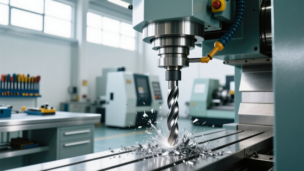
A catastrophic failure of a $185 solid carbide end mill does not merely cost the price of the replacement tool; it risks scrapping a $4,500 Inconel 718 aerospace structural component and causes 45 minutes of unplanned CNC downtime. Establishing rigorous service schedules for cutting tools in milling machine environments requires moving beyond reactive replacement. By implementing predictive maintenance matrices, shops can extend tool life by 20% to 35% while guaranteeing surface finish tolerances.
The Economics of Precision Tool Wear Management
Tooling represents only 3% to 5% of total manufacturing costs, yet tool failure dictates over 20% of unplanned machine stoppages. According to machining guidelines from Sandvik Coromant's milling knowledge base, identifying the specific wear mechanism—whether abrasive flank wear, crater wear, or thermal cracking—is the first step in optimizing replacement intervals. A standardized maintenance schedule ensures that tools are retired at the exact moment their cost-per-part begins to rise due to increased cycle times or secondary deburring requirements.
Daily Visual and Tactile Inspection Protocols
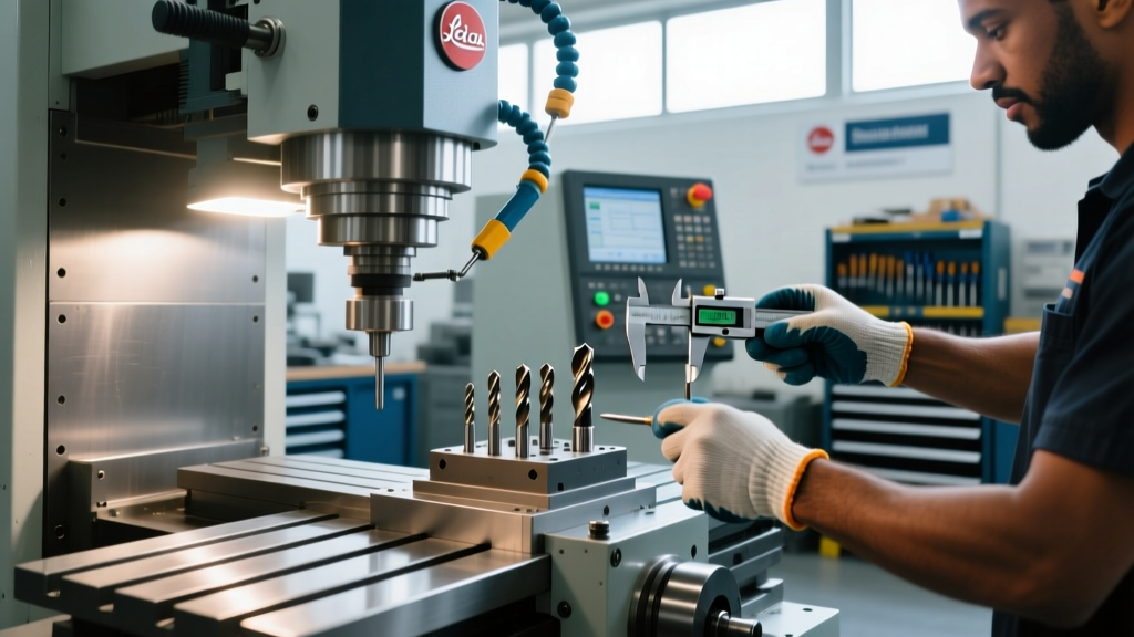
Operators must perform structured inspections at the end of every shift or after completing a critical feature. Relying solely on spindle load meters is insufficient for micro-finishing operations where a 0.002-inch wear land will ruin a part's Ra surface finish.
Solid Carbide End Mill Inspection Criteria
- Flank Wear Land (VB): For finishing 6061-T6 aluminum with a 3-flute AlTiN coated end mill, replace when VB reaches 0.004 inches. For roughing P20 tool steel with a 4-flute TiSiN coated tool, the threshold extends to 0.015 inches.
- Edge Chipping: Inspect the primary cutting edge under 10x magnification. Micro-chipping deeper than 0.001 inches requires immediate tool retirement to prevent catastrophic edge breakdown.
- Built-Up Edge (BUE): Common in gummy materials like 304 stainless steel. If BUE exceeds 15% of the flute depth, increase coolant concentration or switch to a polished-flute geometry.
Do not confuse normal abrasive flank wear with micro-chipping. Flank wear is a gradual, predictable rubbing of the clearance face. Micro-chipping is a mechanical failure of the carbide substrate. Continuing to run a micro-chipped tool will cause the fracture to propagate into the tool body, potentially damaging the toolholder taper and the machine spindle bearings.
Indexable Insert Rotation and Replacement Matrices
Indexable tooling, such as face mills and modular end mills, requires a disciplined rotation schedule to ensure even wear across all pockets. Technical bulletins from Harvey Tool's Machining Resources emphasize that uneven insert seating caused by dirty pockets leads to premature failure of the entire cutter body.
| Tool Type | Material Application | Primary Wear Mechanism | Max Flank Wear (VB) | Service Interval |
|---|---|---|---|---|
| 3" Face Mill (5-Insert) | 4140 Steel (Roughing) | Abrasive / Thermal Cracking | 0.020" | Rotate every 45 mins |
| 90° Square Shoulder Mill | Titanium Ti-6Al-4V | Notch Wear / BUE | 0.008" | Rotate every 20 mins |
| Button Cutter (Round Inserts) | Cast Iron (High Feed) | Crater Wear | 0.015" | Rotate every 90 mins |
Pocket Maintenance Protocol: When rotating inserts, the operator must use a dedicated brass-bristle brush and compressed air to clear the insert pocket. A single 0.005-inch metal chip trapped under the insert will cause it to sit high, taking the entire depth of cut and shattering upon engagement.
Toolholder and Collet Service Intervals
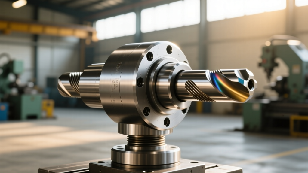
The most meticulously maintained cutting tool will fail prematurely if held in a degraded toolholder. Runout destroys surface finishes and halves tool life. Data compiled by MSC Industrial Supply's Metalworking Insights indicates that maintaining Total Indicated Runout (TIR) below 0.0002 inches is critical for high-performance milling.
ER32 and TG Collet Maintenance Schedule
- Every 40 Hours: Disassemble the collet nut and extractor. Clean the internal taper, collet slots, and nut threads using a specialized collet cleaner and isopropyl alcohol. Never use steel wire brushes on the internal taper.
- Every 120 Hours: Inspect the collet for permanent deformation. If the collet requires excessive force to seat into the nut, the slotted spring steel has fatigued. Replace the collet immediately.
- Every 500 Hours: Measure TIR at 3x diameter extension using a dial indicator. If TIR exceeds 0.0003 inches on a standard ER system, retire the collet and inspect the toolholder taper for fretting corrosion.
Hydraulic and Shrink-Fit Toolholders
Hydraulic chucks rely on internal fluid bladders. If the chuck loses clamping force, the tool will pull out during heavy axial engagement. Test hydraulic pull-out force annually using a tension gauge. For shrink-fit holders, the thermal expansion and contraction cycles eventually alter the metallurgical grain structure. Anneal and recalibrate shrink-fit holders every 2,000 heating cycles to prevent permanent bore expansion.
Coolant Chemistry and Delivery Maintenance
Cutting fluid is not merely a flushing agent; it is a chemical boundary lubricant that directly dictates tool wear rates. A drop in water-soluble semi-synthetic coolant concentration from 9% to 5% accelerates flank wear on uncoated carbide by up to 30% due to the loss of extreme pressure (EP) additives.
- Daily: Check concentration using a handheld refractometer. Maintain between 8% and 10% depending on the manufacturer's specification.
- Weekly: Test pH levels. A pH below 8.5 indicates bacterial growth, which breaks down the emulsion and causes rust on the machine ways and the workpiece.
- Monthly: Skim tramp oil and clean the coolant tank reservoir. Tramp oil coats the cutting tool, preventing the water-based coolant from reaching the cutting edge, leading to localized thermal shock and micro-cracking.
Transitioning to Predictive Spindle Load Monitoring
Modern 2026 CNC controls equipped with edge-computing capabilities allow shops to move from time-based maintenance to condition-based maintenance. By establishing a baseline spindle load signature for a specific toolpath and material, the control can detect the subtle 2% to 4% increase in amperage draw that indicates progressive flank wear.
Set macro-level alarms in the CNC controller to pause the machine and prompt an operator inspection when the spindle load deviates by more than 8% from the baseline average over three consecutive passes. This prevents the tool from reaching catastrophic failure thresholds while squeezing maximum usable life out of premium carbide geometries.
Frequently Asked Questions
How does through-tool coolant pressure affect insert seating and maintenance?
High-pressure through-tool coolant (1,000+ PSI) can force microscopic swarf into the threads of modular tooling and indexable insert screws. When servicing high-pressure tooling, always apply a high-temperature anti-seize compound (such as molybdenum disulfide) to the insert Torx screws. Without this, the screws will gall and seize inside the cutter body, requiring EDM extraction and ruining the toolholder.
What is the acceptable TIR for roughing vs. finishing end mills?
For roughing operations utilizing trochoidal milling paths, a TIR of up to 0.0005 inches is generally acceptable, as the radial engagement is low and the chip load is distributed dynamically. However, for finishing operations where the tool is engaged radially up to 50% of its diameter, TIR must be held to 0.0002 inches or less. Excessive runout in finishing causes one flute to do all the work, leading to rapid localized wear and poor surface finish.
Should I use a tool presetter for manual milling machine operations?
While tool presetters are standard in CNC environments, they are highly valuable for manual milling machines equipped with Digital Readouts (DROs). Presetting tools offline saves 3 to 5 minutes of machine downtime per tool change. More importantly, a high-quality optical presetter allows the manual machinist to inspect the cutting edge under 20x magnification before the tool ever touches the machine, catching micro-chips and coating defects that would otherwise ruin a manual setup.