Motorized Material Handling Equipment: Bridge Crane Schedules
Detailed maintenance schedules for overhead and bridge crane configurations. Keep your motorized material handling equipment OSHA-compliant and efficient.
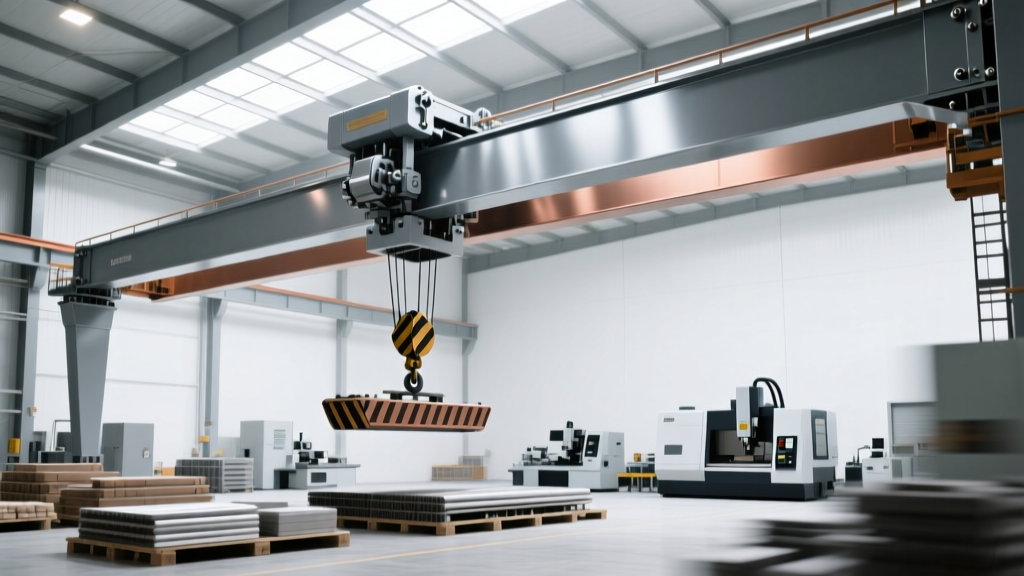
Overhead bridge cranes represent the highest risk-to-reward ratio in heavy industrial maintenance planning. When managing a fleet of motorized material handling equipment, these systems demand rigorous adherence to OSHA 1910.179 and ASME B30.2 standards. Unlike ground-level forklifts or AGVs, a failure in a 30-ton double-girder bridge crane does not merely halt production; it introduces catastrophic safety liabilities. Effective servicing requires moving beyond generic lubrication checklists to target the specific electromechanical tolerances of hoist motors, trolley drives, and bridge electrification systems.
Motorized Drive Configurations in Bridge Cranes
Before establishing a service cadence, maintenance teams must classify the specific motorized configurations operating on their bridge cranes. Modern systems typically utilize one of three drive setups, each requiring distinct diagnostic approaches:
- AC Wound Rotor Motors with Stepless Contactors: Traditional setups requiring frequent inspection of carbon brushes, slip rings, and resistor banks. Dust accumulation on resistor grids is a primary cause of overheating.
- AC Squirrel Cage Motors with Variable Frequency Drives (VFDs):strong> The current industry standard for precise load control. Maintenance shifts from mechanical contactors to electronic thermal management, specifically VFD cooling fans and harmonic filter capacitors.
- DC Hoist Motors: Found in older or highly specialized heavy-lift applications. These demand strict commutator undercutting and brush tension calibration.
The Preventative Maintenance Matrix
The following matrix outlines the mandatory service intervals for motorized bridge crane components. These schedules align with Crane Manufacturers Association of America (CMAA) specifications for Class C (Moderate) through Class F (Heavy Continuous) service.
| Component | Daily (Pre-Shift) | Monthly | Semi-Annual | Annual |
|---|---|---|---|---|
| Hoist & Trolley Brakes | Functional test (no load) | Measure lining thickness | Adjust torque settings | Replace pins/clevises |
| VFD / Control Panels | Check error codes/fans | Clean intake filters | Thermographic scan | Capacitor ESR testing |
| Gearboxes (Hoist) | Visual leak check | Check sight glass level | Oil particle analysis | Change oil (ISO VG 220) |
| Bridge Drive Wheels | Listen for flange squeal | Inspect for flat spots | Measure flange wear | Ultrasonic bearing test |
| Festoon / Conductor Bar | Visual cable sag check | Inspect trolley rollers | Clean conductor dust | Replace worn collectors |
Hoist Motor and Brake Tolerances: The Critical Numbers
General inspections are insufficient for motorized material handling equipment operating near capacity. Technicians must measure against exact engineering tolerances. The hoist brake is the single most critical safety mechanism on the crane.
Brake Lining and Torque Specifications
Most industrial bridge cranes utilize DC injection or AC electromagnetic disc brakes. The brake lining must be replaced before it wears down to the rivet heads or the manufacturer's minimum threshold, typically 1/16 inch (1.5mm). When adjusting the brake spring torque, technicians must ensure the brake can hold 125% of the rated load statically. If a 20-ton hoist is tested, the brake must hold 25 tons without slip during the annual load test.
Motor Insulation Resistance (Megger Testing)
Hoist motors are subjected to high thermal cycling and conductive metallic dust. Annual maintenance must include an insulation resistance test using a megohmmeter. Applying 500V DC to the motor windings relative to the frame should yield a minimum reading of 2.0 megohms. Readings below 1.0 megohm indicate moisture ingress or insulation breakdown, requiring immediate varnish treatment or rewinding before the motor is re-energized.
WARNING: VFD Bearing FlutingWhen retrofitting older bridge cranes with modern VFDs, common mode voltages can discharge through the motor shaft, causing electrical discharge machining (EDM) fluting in the motor bearings. If your hoist motor fails prematurely after a VFD upgrade, install an AEGIS shaft grounding ring to divert stray currents away from the bearings.
Wire Rope and Sheave Discard Criteria
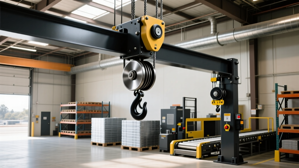
The motorized hoist drum and wire rope assembly require meticulous evaluation. According to ASME B30.2 standards, wire rope must be removed from service immediately if any of the following conditions are met:
- Broken Wires: Six or more broken wires in one rope lay, or three or more broken wires in one strand of a lay.
- Diameter Reduction: Loss of more than 1/3 of the original diameter of the outside wires, or a 3% reduction in the nominal rope diameter due to core failure.
- Sheave Groove Wear: If the hoist sheave grooves wear unevenly, they will crush the new wire rope upon installation. Use a sheave gauge to verify the groove radius matches the rope diameter within a 0.015-inch tolerance.
Electrification Festoon Edge Cases
The festoon system—the motorized cable management track that follows the trolley—is a frequent source of unplanned downtime. A common edge-case failure occurs when the trolley tow arm misaligns, causing the C-track rollers to bind. This increases the amperage draw on the trolley drive motor, eventually tripping the VFD overload fault. To prevent this, maintenance teams must measure the festoon loop sag. The loops should never drop below the bottom flange of the bridge girder. If the neoprene cable jackets show micro-cracking from continuous flexing, replace the flat cables with high-flex robotic-rated cables (e.g., 10-million cycle rated) to prevent internal copper strand fracture that standard continuity tests might miss.
Financial ROI by CMAA Service Class
Aligning your maintenance budget with the crane's CMAA Service Class prevents both over-maintenance and catastrophic neglect. Unplanned downtime for a 30-ton double-girder bridge crane costs roughly $1,200 to $2,500 per hour in halted downstream production lines.
'A facility running a CMAA Class E (Heavy) crane on a Class C (Moderate) maintenance schedule will experience a hoist gearbox failure approximately every 14,000 operating hours. Rebuilding a 50-ton hoist gearbox costs between $18,000 and $24,000, whereas annual ferrographic oil analysis and scheduled synthetic lubricant changes cost under $800 per year.' - Industrial Reliability Engineering Report
For facilities operating motorized material handling equipment in severe environments (such as steel mills or foundries), transitioning from time-based maintenance to condition-based monitoring—utilizing vibration analysis on the bridge drive gearboxes and thermal imaging on the mainline conductor bars—yields a 30% reduction in annual servicing costs while maintaining strict OSHA compliance.