Material Handling Equipment Design: Dock Leveler Mechanics Explained
Explore how material handling equipment design dictates dock leveler mechanics, hydraulic specs, and loading bay safety standards for modern operations.
The Biomechanics of Dock Levelers in Material Handling Equipment Design
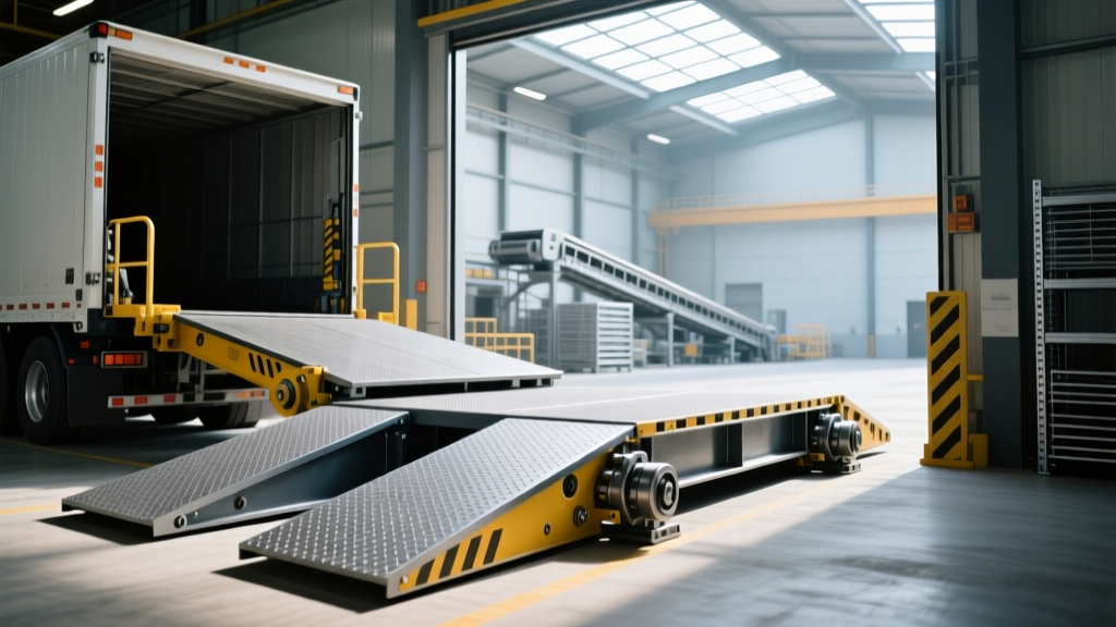
Dock levelers represent a critical intersection of structural metallurgy, fluid dynamics, and automated safety logic. When evaluating material handling equipment design, the loading dock leveler is often the most heavily abused asset in the supply chain. It must endure thousands of dynamic impact cycles annually from 15,000-pound forklifts while maintaining a seamless bridge between a static warehouse floor and a floating truck bed. Understanding the technical specifications, load kinematics, and actuation mechanics of these systems is essential for facility engineers and procurement managers aiming to minimize downtime and ensure ANSI compliance.
Rolling Load Limit (RLL) vs. Static Capacity Calculations
A common engineering failure in facility planning is confusing a leveler's static load capacity with its Rolling Load Limit (RLL). According to guidelines published by the Dock Equipment Manufacturers Association (DEA), a leveler rated for a 30,000 lb static capacity does not mean it can support a 30,000 lb stationary load. Instead, RLL calculates the maximum weight of a moving three-wheel forklift and its payload that can safely cross the leveler without causing permanent structural deflection.
For a standard 8-foot by 10-foot hydraulic leveler, a 50,000 lb RLL rating typically requires a minimum 3/16-inch thick steel tread plate on the deck and a 3/4-inch thick steel lip. The dynamic force exerted by a forklift's drive tires hitting the lip hinge creates a momentary impact multiplier of up to 1.5 times the static weight, necessitating heavy-duty structural tubing in the undercarriage.
Actuation Systems: Engineering and Performance Matrix
The method of actuation defines the maintenance lifecycle, energy consumption, and operational speed of the loading bay. Below is a technical comparison of the three primary actuation architectures utilized in modern facilities.
| Specification | Hydraulic (Standard) | Mechanical (Spring-Biased) | Pneumatic (Air-Bag) |
|---|---|---|---|
| Actuation Mechanism | 1.5 HP HPU, dual hydraulic cylinders | Heavy-duty extension springs, manual pull-chain | Low-pressure air compressor, reinforced neoprene bellows |
| Lip Control | Independent lip cylinder with flow-control valve | Gravity drop with mechanical snubber | Gravity drop with pneumatic dampening |
| Typical 2026 Pricing | $4,500 - $6,200 | $2,800 - $3,900 | $3,500 - $5,000 |
| Maintenance Interval | Bi-annual fluid and seal inspection | Monthly spring tension and hinge lubrication | Annual air-bag inspection for dry-rot/tears |
| Free-Fall Protection | Hydraulic velocity fuses (automatic) | Requires secondary mechanical safety legs | Requires secondary mechanical safety legs |
Hydraulic Power Unit (HPU) Engineering & Cold-Weather Cavitation
In hydraulic material handling equipment design, the HPU is the central nervous system of the dock leveler. A standard industrial HPU utilizes a 1.5 HP, 115V AC or 24V DC motor driving a gear pump that delivers 1.2 to 1.5 gallons per minute (GPM) at operating pressures between 1,200 and 1,800 PSI.
Engineering Warning: Cold-Weather Fluid CavitationFacilities operating in sub-40°F (4°C) environments frequently experience HPU cavitation. Standard ISO 32 hydraulic fluid thickens in unheated loading bays, causing the gear pump to starve and pull air into the lines. This results in a spongy lift cycle and severe pump scoring. Solution: Specify synthetic ISO 15 or ISO 22 hydraulic fluids for unheated docks, or integrate a 120V silicone heating pad wrapped around the HPU reservoir tank, set to activate at 45°F.
Lip Actuation Kinematics
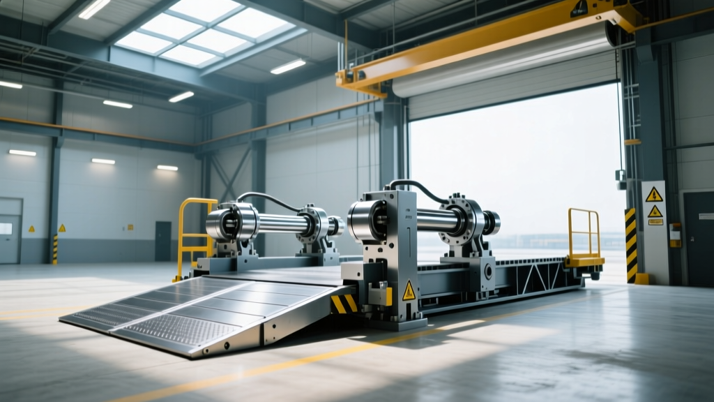
The lip cylinder operates on a separate hydraulic circuit or a sequenced valve block from the main lift cylinder. As the main cylinder raises the deck to its apex (typically 12 to 16 inches above dock height), a limit switch or mechanical cam triggers the lip valve. The lip extends outward by 16 to 20 inches. The critical engineering parameter here is the lip crown radius. A machined 1.5-inch radius on the underside of the lip hinge ensures smooth transition for forklift tires, reducing the vertical shock load transferred to the forklift's mast and the operator's spine.
Structural Decking and Hinge Fatigue Analysis
The most common catastrophic failure point in loading bay equipment is the lip hinge. The hinge must endure continuous shear stress and rotational fatigue.
Open vs. Closed Hinge Architectures
- Open Hinge Design: Utilizes alternating steel loops welded to the deck and lip, joined by a continuous 1-inch or 1.25-inch diameter steel pin. While cost-effective, open hinges allow debris (shrink wrap, wooden pallet splinters) to infiltrate the pin bore, accelerating wear and causing the pin to seize.
- Closed (Full-Width) Hinge Design: Features a continuous steel tube welded across the entire width of the deck and lip, with an internal solid steel pin. This design completely excludes debris from the friction zone, increasing the hinge lifecycle by up to 300% in high-throughput, multi-shift environments. Specify closed hinges when processing over 50 trailers per day.
ANSI MH30.1 Compliance and Safety Interlocks
Adherence to OSHA 1910.176 and the ANSI MH30.1 standard dictates that dock levelers must integrate with vehicle restraints to prevent premature trailer departure (trailer creep). In 2026, state-of-the-art material handling equipment design relies on PLC-driven interlock matrices rather than simple mechanical limit switches.
- Step 1: Restraint Engagement. The hydraulic vehicle restraint (e.g., a RIG barrier) hooks the trailer's rear impact guard (ICC bar). A proximity sensor confirms the hook is fully engaged.
- Step 2: Leveler Enablement. The PLC receives the restraint signal and illuminates the green interior light, simultaneously unlocking the dock leveler's push-button control panel.
- Step 3: Cross-Traffic Detection. Ultrasonic sensors mounted in the pit detect if the leveler is in the stored (cross-traffic) position. If a forklift approaches while the leveler is stored but the door is open, an audible alarm triggers.
- Step 4: Lip Verification. A linear transducer on the lip cylinder confirms the lip is fully extended and resting on the truck bed before the system allows the forklift to cross.
'Modern dock leveler design is no longer just about moving a steel plate up and down. It is about creating a closed-loop data environment. By integrating linear position sensors on the main cylinder, facility managers can now track exact dock-door utilization times and predict HPU motor failure based on thermal cycle data before a breakdown occurs.'
— Dr. Aris Thorne, Lead Systems Engineer, Industrial Automation Logistics Group
Troubleshooting Decision Tree: Hydraulic Leveler Failures
When a hydraulic dock leveler fails to operate correctly, maintenance teams should follow this diagnostic sequence to isolate the mechanical or electrical fault:
Symptom: Deck Lifts, but Lip Does Not Extend
- Check 1: Inspect the lip actuation limit switch. If the deck reaches full height but the switch is misaligned, the lip solenoid will never receive the 24V signal.
- Check 2: Examine the lip flow-control valve. If clogged with metallic particulate from a degrading pump, the lip will extend sluggishly or not at all.
- Check 3: Verify lip hinge lubrication. Seized hinges will create resistance that exceeds the lip cylinder's 800 lb push-force capacity.
Symptom: Leveler Drops Prematurely When Loaded
- Check 1: Test the hydraulic holding valve (counterbalance valve). Internal seal bypass will allow fluid to leak back into the reservoir under heavy load.
- Check 2: Inspect the main cylinder piston seals. Fluid bypassing the piston will result in a slow, continuous descent while a forklift is staged on the deck.
By prioritizing precise material handling equipment design parameters—specifically RLL calculations, closed-hinge metallurgy, and PLC-integrated safety interlocks—facility operators can drastically reduce loading bay bottlenecks and eliminate the structural fatigue that leads to catastrophic dock accidents.