Fixed Bridge CNC Machining Centers: Aerospace & Energy Case Studies
Discover how fixed bridge CNC machining centers tackle massive aerospace and energy parts. Real case studies, ROI data, and rigidity specs inside.
The Architecture of Rigidity: Why Fixed Bridge?
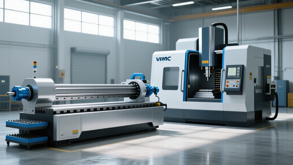
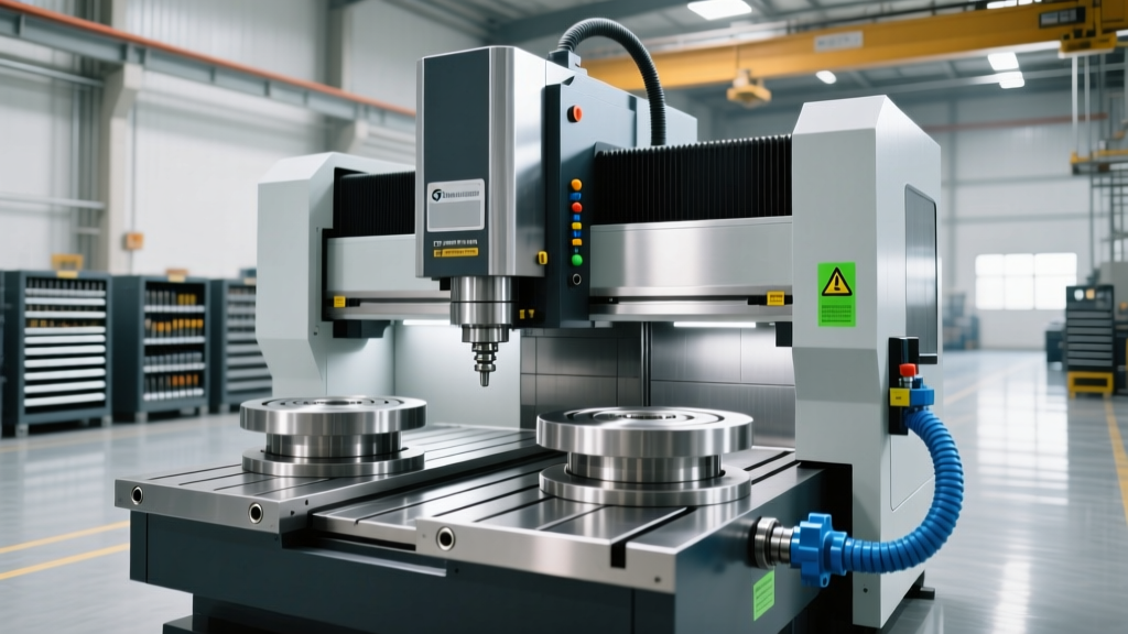
In heavy-duty and large-format manufacturing, machine tool kinematics dictate the absolute limits of geometric accuracy and material removal rates (MRR). While moving-bridge (gantry) and moving-column configurations dominate general large-part machining, fixed bridge CNC machining centers occupy a highly specialized tier. In a fixed bridge architecture, the massive crossrail and columns are rigidly anchored to the foundation, while the worktable moves longitudinally along the X-axis. The saddle traverses the fixed bridge in the Y-axis, and the spindle ram extends in the Z-axis.
This design completely eliminates the dynamic compliance issues associated with accelerating and decelerating multi-ton bridge structures. For aerospace structural components exceeding 10 meters in length, or energy sector castings weighing over 30 metric tons, the fixed bridge configuration provides unmatched static and dynamic stiffness. The following case studies and engineering data illustrate how this architecture solves specific manufacturing bottlenecks in 2026.
Engineering Data Highlight: Dynamic Stiffness at the Tool Center Point (TCP)- Moving Bridge (Gantry): 15 - 25 N/μm (varies heavily with Y-axis position)
- Moving Column: 18 - 30 N/μm (degrades at maximum Z-extension)
- Fixed Bridge: 40 - 65 N/μm (consistent across the entire Y and Z travel envelope)
Case Study 1: Aerospace Ti-6Al-4V Wing Spar Profiling
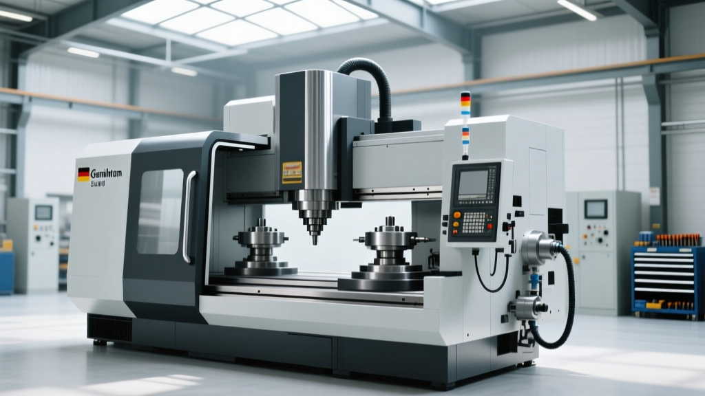
Machining titanium wing spars from solid billet involves removing up to 90% of the starting material. The alpha-beta Ti-6Al-4V alloy generates immense cutting forces and localized heat, demanding a machine tool that resists chatter at high torque outputs. A Tier-1 aerospace supplier recently integrated a Handtmann PBZ (Profile Machining Center), a premier fixed bridge machine specifically engineered for long aerospace profiles.
The Machining Challenge
The target component was a 9.5-meter continuous wing spar with deep, thin-walled pockets (wall thickness down to 2.5mm). Previous attempts on a moving-gantry mill resulted in severe Z-axis deflection and chatter marks during deep-cavity roughing, forcing a 40% reduction in feed rates to maintain surface finish requirements.
Fixed Bridge Solution & Metrics
By utilizing the fixed bridge architecture, the Y-axis and Z-axis masses remain stationary relative to the cutting forces, isolating the dynamic variables to the X-axis table movement. The Handtmann PBZ utilized a high-torque motor spindle delivering 850 Nm of continuous torque at low RPMs (critical for titanium).
- Roughing Strategy: Dynamic trochoidal milling with 65% radial engagement and high axial depth of cut (up to 1.5x cutter diameter).
- Achieved MRR: 185 cm³/min in Ti-6Al-4V (up from 110 cm³/min on the previous gantry mill).
- Tool Life Extension: End mill life increased by 34% due to the elimination of micro-vibrations at the tool tip, as confirmed by Sandvik Coromant titanium machining guidelines which emphasize machine stiffness as the primary variable in titanium tool wear.
- Geometric Accuracy: True position of deep-pocket floor features held within 0.015mm over the 9.5-meter length, aided by the machine's integrated thermal growth compensation system.
Case Study 2: Ductile Iron Wind Turbine Main Shafts
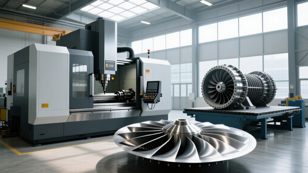
The transition to 15+ MW offshore wind turbines has drastically increased the physical scale of drivetrain components. Main shaft housings cast from GGG-40 ductile iron now routinely exceed 25 metric tons. Machining the main bearing journals and flange faces on these massive parts introduces severe stick-slip friction if the machine's guideways are inadequate.
Waldrich Coburg PowerCut Implementation
A European heavy machinery manufacturer deployed a Waldrich Coburg PowerCut fixed bridge machining center to handle these oversized energy components. The defining feature of this installation was the use of fully enclosed hydrostatic guideways for the X-axis table movement.
'When moving a 30-ton casting on linear roller guides, the breakaway friction causes micro-stuttering (stick-slip), which ruins the surface finish of large bore machined surfaces. Hydrostatic ways float the table on a pressurized oil film, reducing the friction coefficient to near-zero and enabling perfectly smooth contouring at low feed rates.' — Lead Manufacturing Engineer, Heavy Drivetrain Division.
Performance Outcomes
The fixed bridge design allowed the heavy casting to move longitudinally while the 100 kW milling head remained on the ultra-rigid stationary bridge. This prevented the Y-axis drive motors from having to accelerate the combined mass of the bridge and the part simultaneously. The result was a 22% reduction in cycle time for the main journal boring operations and the elimination of scraped bearing surfaces due to chatter.
Kinematic Comparison Matrix
Selecting the right large-format architecture requires matching the machine's physical traits to the part's mass and geometry. The table below provides a procurement framework for manufacturing engineers.
| Machine Architecture | Optimal Part Weight | Optimal Part Geometry | Primary Limitation | Typical Price Range (2026) |
|---|---|---|---|---|
| Fixed Bridge | 15 to 60+ Metric Tons | Long, heavy profiles; massive cubic castings | Requires massive, isolated foundation; large shop footprint | $2.8M - $5.5M+ |
| Moving Bridge (Gantry) | 5 to 25 Metric Tons | Wide, flat panels; complex 5-axis contours | Y-axis dynamic stiffness drops at extreme crossrail travel | $1.5M - $3.8M |
| Moving Column | 2 to 10 Metric Tons | Medium dies, mold bases, general prismatic parts | Z-axis overhang causes pitch/yaw errors at full extension | $850k - $2.2M |
The Hidden Costs: Foundation and Installation Realities
Purchasing a fixed bridge CNC machining center extends far beyond the machine's base price. Because the bridge is fixed directly to the floor, the machine's accuracy is entirely dependent on the stability of the foundation. According to Modern Machine Shop heavy machining reports, improper foundation preparation is the leading cause of geometric drift in large-format machines during their first year of operation.
⚠️ Installation Warning: Never mount a fixed bridge machine to a standard factory slab. The X-axis table movement generates low-frequency seismic waves that will reflect off standard footings and distort the bridge's alignment.Required Foundation Specifications
- Isolated Concrete Block: The machine must sit on a dedicated, steel-reinforced concrete mass that is physically separated from the surrounding factory floor by a 50mm gap filled with high-damping polyurethane or cork-rubber composites.
- Mass Ratio: The concrete foundation mass should be a minimum of 2.5 to 3 times the total moving mass of the machine and workpiece combined.
- Natural Frequency Tuning: The foundation must be engineered so its natural resonant frequency is strictly below 5 Hz, ensuring it does not amplify the 15-40 Hz frequencies generated by heavy milling spindles and coolant pumps.
- Thermal Isolation: In facilities with significant ambient temperature swings, the foundation must include sub-slab insulation to prevent ground thermal expansion from twisting the fixed bridge columns.
Procurement Decision Framework
When evaluating capital expenditure for large-format CNC equipment in 2026, use this decision tree to justify a fixed bridge investment:
- If your parts are under 8 metric tons and under 4 meters long: A moving column or moving bridge is more cost-effective and requires less floor space.
- If you machine 5-axis aerospace monolithic structures (e.g., ribs, spars) longer than 6 meters: A fixed bridge profile machining center (like the Handtmann PBZ) is mandatory to maintain Z-axis rigidity and prevent thin-wall chatter.
- If you machine heavy energy/industrial castings (>20 tons) requiring heavy boring and facing: A fixed bridge with hydrostatic guideways (like Waldrich Coburg or SNK configurations) is the only viable option to eliminate stick-slip and maintain micron-level bore tolerances.
Ultimately, fixed bridge CNC machining centers represent the apex of static rigidity. While the initial capital and infrastructure costs are substantial, the reduction in scrapped mega-parts, extended tool life in exotic alloys, and elimination of secondary hand-scraping operations yield a compelling ROI for high-mix, heavy-industry manufacturers.