CNC Multi-Axis Machining: Advanced Operator Training Best Practices
Master CNC multi-axis machining with advanced operator training protocols, collision avoidance strategies, and 5-axis setup best practices.
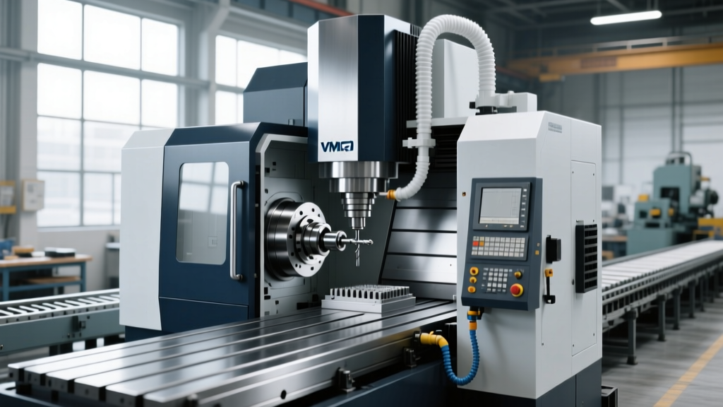
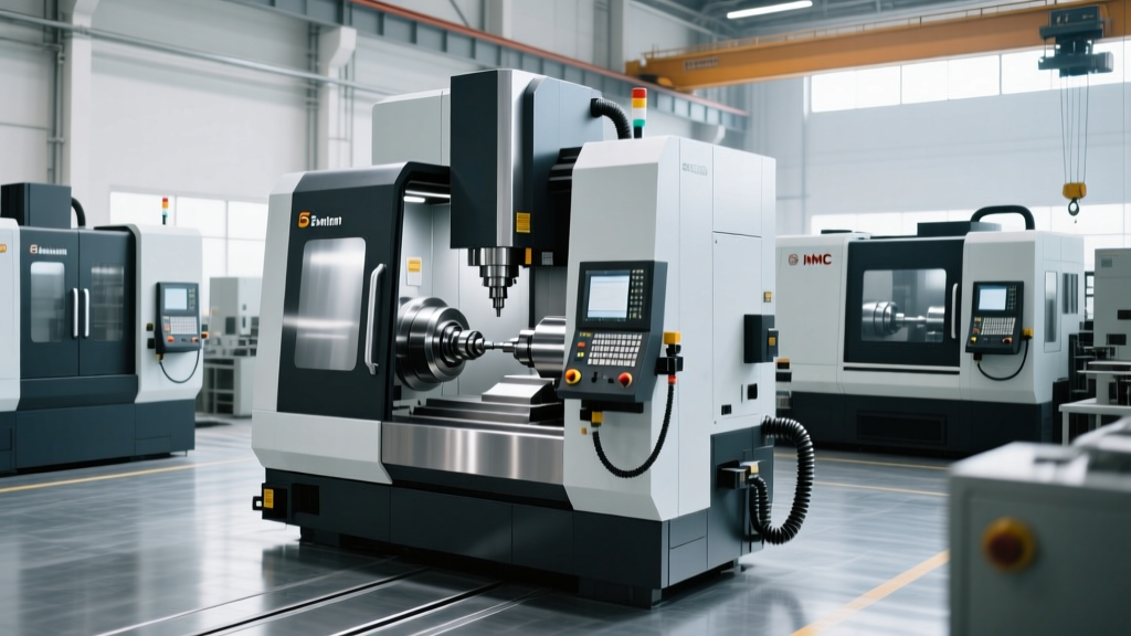
A single crash on a 5-axis trunnion table or swivel head does not just break a $100 end mill. Impacting a high-speed 15,000+ RPM spindle (common on models like the Haas UMC-750SS2 or DMG MORI DMU 50 3rd Generation) typically results in $45,000 to $85,000 in spindle rebuild costs, ruined trunnion bearings, and 4 to 8 weeks of machine downtime. CNC multi-axis machining requires a fundamental shift from reactive button-pushing to proactive kinematic management.
The Multi-Axis Paradigm Shift: 3-Axis vs. 5-Axis
Operators transitioning from standard 3-axis Vertical Machining Centers (VMCs) to CNC multi-axis machining often rely on habits that are actively dangerous on a 5-axis machine. In a 3-axis environment, the Work Coordinate System (WCS) is static, and toolpaths are strictly linear relative to the table. In simultaneous 5-axis machining, the WCS is dynamic, and the tool vector constantly shifts relative to the part.
| Operational Concept | 3-Axis VMC Mindset | 5-Axis Multi-Axis Mindset |
|---|---|---|
| Work Coordinate System (WCS) | Fixed to the vise or fixture; Z-axis is always perpendicular to the table. | Dynamic; Z-axis tool vector tilts and rotates relative to the part surface normal. |
| Tool Length Compensation | Standard G43 H-code; measures Z-distance from gauge line to tip. | Requires RTCP (G43.4/G43.5); control calculates pivot point offsets dynamically. |
| Clearance Zones | Retract to Z-home or safe plane above the part. | Retract moves must account for rotary axis sweep; Z-home can drive the tool into the table if tilted. |
| Proving Out Code | Dry run with Z-axis shifted up 2 inches; single block execution. | Virtual commissioning via kinematic simulation software prior to shop floor execution. |
Mastering RTCP (Rotary Tool Center Point) Kinematics
The most critical technical concept in CNC multi-axis machining is RTCP. When RTCP is active (typically invoked via G43.4 on Fanuc/Haas or TRAORI on Siemens Sinumerik controls), the CNC controller continuously calculates the inverse kinematics required to keep the tool tip exactly on the programmed XYZ coordinate, even as the rotary axes (A/B or B/C) move simultaneously.
Calibration and Tolerancing
If the machine's physical pivot points do not perfectly match the mathematical model in the controller, RTCP will drive the tool off the programmed path, causing gouges or crashes. Operators must be trained to perform routine kinematic calibration.
- Equipment: Use a Renishaw AxiSet Check Gauge or a Heidenhain KinematicsOpt touch probe cycle.
- Frequency: Calibrate weekly, or immediately after any machine collision, heavy crash, or significant ambient temperature shift (greater than 10°F in the shop).
- Tolerance Targets: For aerospace and medical titanium machining, pivot point errors must be mapped to within 0.0002" (5 microns). For general aluminum structural parts, 0.0005" is acceptable.
"Operators often assume RTCP is a 'set and forget' parameter. In reality, thermal growth in the trunnion bearings and harmonic wear on the roller gear cam drives shift the physical pivot points daily. Probing the kinematic center at the start of every shift is non-negotiable for tight-tolerance multi-axis work."
Virtual Commissioning and Collision Avoidance
Proving out 5-axis G-code on the shop floor using "single block" and "rapid override" is an obsolete and highly dangerous practice. The spatial complexity of simultaneous multi-axis moves means human operators cannot visually predict the swept volume of the tool holder and spindle nose during rapid traverse.
Mandatory Simulation Protocols
According to CGTech (VERICUT), virtual commissioning must simulate the exact kinematic chain, tool assembly, and raw stock of the specific machine. Training programs must require operators to build and verify digital twins before loading code onto the physical machine.
- Model Accuracy: Ensure the simulation software contains the precise 2026 machine model, including the exact trunnion platen T-slot layout, spindle nose geometry, and tool changer arm sweep zones.
- Tool Assembly Mapping: Simulate the entire tool assembly, including the retention knob, tool holder (e.g., HSK-A63 or CAT40), shrink-fit extension, and the cutting tool. Do not rely on default library tools.
- Stock Model Verification: Import the exact near-net-shape casting or forging STL file, not just the finished CAD model, to detect collisions on uneven raw stock surfaces during initial facing operations.
Workholding Strategies for Simultaneous 5-Axis
Standard 6-inch machinist vises are inadequate for CNC multi-axis machining. The rotary axes require the tool to access five sides of the part, meaning the workholding must have a minimal footprint and high clamping force to resist lateral cutting deflection.
Dovetail and Hydraulic Workholding
Operators must be trained in the preparation and setup of specialized 5-axis workholding:
- Dovetail Workholding: Using systems like the Schunk Kontec or Mitee-Bite Pitbull clamps requires operators to machine a precise dovetail profile into the raw stock (usually 0.150" deep with a 45° or 60° angle). Training must cover the exact feed rates and toolpaths for cutting these retention features in hard materials like Inconel 718 or 17-4 PH stainless without work-hardening the grip zone.
- Clearance Angles: Operators must understand the concept of the "tool tilt clearance cone." If a part is clamped on a 40mm riser, the operator must calculate the maximum safe tilt angle before the spindle nose or tool holder flange intersects with the vise jaws or riser block.
- Hydraulic Fixturing: For high-volume production, training on hydraulic pump pressure settings is vital. Over-pressurizing thin-walled aerospace brackets during 5-axis clamping induces elastic deformation, resulting in out-of-tolerance parts once the pressure is released.
Tooling Stickout and L:D Ratios in Multi-Axis
Multi-axis toolpaths often require reaching deep into pockets while the spindle is tilted at 30° to 45°. This exacerbates tool deflection and chatter. Sandvik Coromant Milling Knowledge guidelines emphasize strict adherence to Length-to-Diameter (L:D) ratios.
Data Highlight: Tool Overhang Limits for 5-Axis Roughing- Solid Carbide End Mills: Maximum L:D ratio of 4:1. Beyond this, harmonic chatter will destroy surface finish and accelerate flank wear.
- Heavy Metal / Tungsten Alloy Shanks: Maximum L:D ratio of 6:1. Required for deep cavity milling in titanium where standard steel shanks deflect.
- Tool Holder Selection: Shrink-fit holders are mandatory for 5-axis clearance due to their slim profile and high gripping force (up to 4x stronger than standard set-screw holders). Hydraulic chucks should be reserved for finishing operations where vibration dampening is prioritized over extreme clamping force.
Troubleshooting Multi-Axis Chatter and Deflection
When chatter occurs during a 5-axis contouring pass, operators must know how to diagnose the root cause without blindly reducing feed rates, which kills cycle time and work-hardens materials.
| Symptom | Probable Cause | Operator Corrective Action |
|---|---|---|
| High-pitch squeal during tilted finishing passes | Tool tip speed is zero or near-zero at the center of the ball end mill. | Increase lead/tilt angle to 15°-20° to engage the cutting edge on the tool's periphery rather than the dead center. |
| Low-frequency vibration and poor surface finish | Part or fixture deflection due to inadequate clamping force on the C-axis. | Verify dovetail engagement depth; reduce radial depth of cut (RDOC) by 30% and increase spindle RPM to match the machine's sweet spot. |
| Gouging at the start of a 5-axis contour | RTCP activation delay or incorrect tool length measurement. | Re-measure tool length using the spindle probe; ensure G43.4 is called on a linear move prior to any rotary axis engagement. |
Certification and Continuous Skill Validation
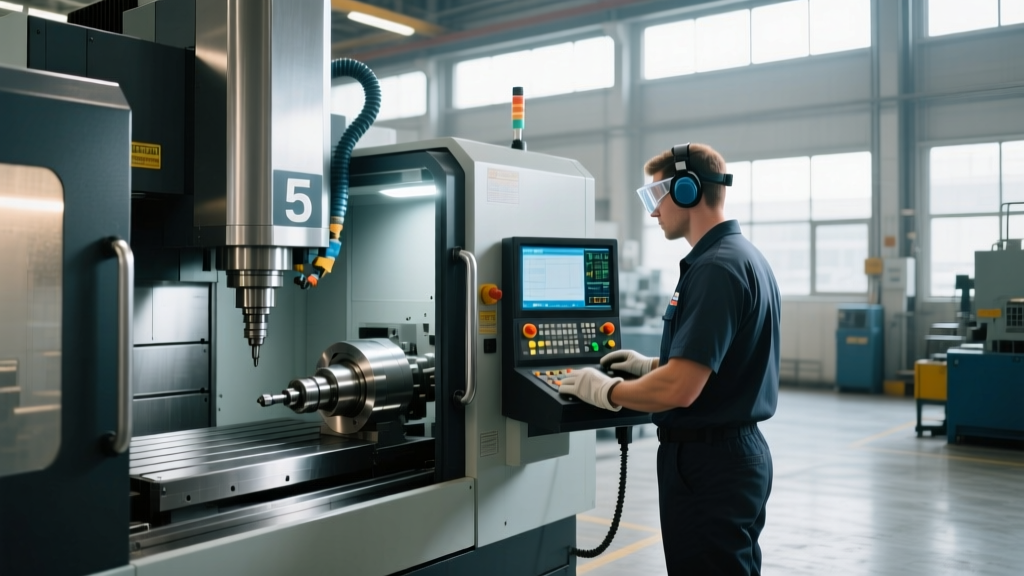
Because the financial risks of CNC multi-axis machining are so high, shops must move beyond informal "shadowing" training. Operators should be required to achieve formal validation. The National Institute for Metalworking Skills (NIMS) offers multi-axis CNC milling credentials that test both theoretical kinematics and practical setup capabilities.
A robust 2026 training program mandates that operators pass a virtual simulation crash-test—where they are intentionally given flawed G-code and incorrect tool assemblies in VERICUT—and successfully identify and correct the collision points before they are ever cleared to load a program onto a physical $500,000 multi-axis machining center.