CNC Vertical Machining Center Mechanics: Specs & How It Works
Explore the technical specifications and internal mechanics of a CNC vertical machining center. Learn how VMC spindles, axes, and controls operate.
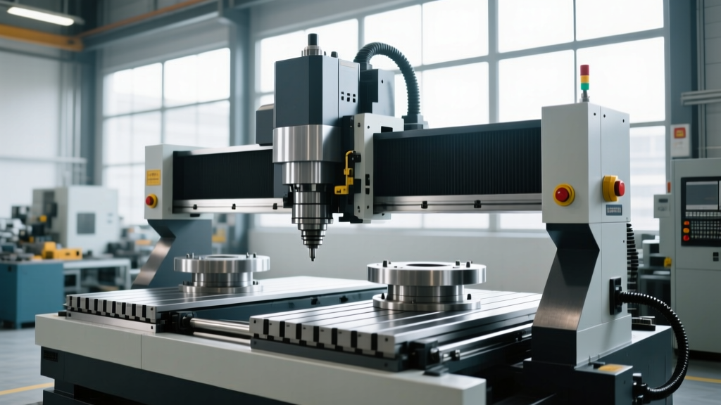
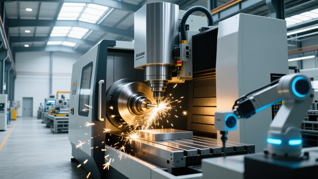
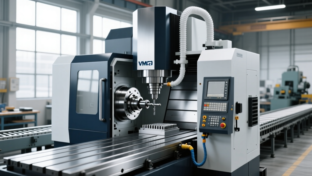
A CNC vertical machining center (VMC) orients its primary spindle along the Z-axis, perpendicular to the horizontal worktable. This fundamental architectural choice leverages gravity to optimize chip evacuation, prevent recutting, and simplify fixture design. However, beneath the sheet metal enclosure lies a complex integration of kinematics, thermal management, and servo-feedback loops that dictate the machine’s ultimate precision and material removal rate (MRR).
Structural Kinematics: C-Frame vs. Bridge-Type Architectures
The structural foundation of any VMC determines its dynamic stiffness and geometric accuracy under load. Manufacturers generally deploy one of two primary column designs:
1. The C-Frame (Cantilever) Design
Standard in entry-level and mid-range machines (such as the Haas VF-Series), the C-frame features a single rear column supporting the spindle head. While cost-effective and offering excellent operator access on three sides, the C-frame is inherently susceptible to pitch and yaw errors when the X-axis saddle extends to its maximum travel limits. To counteract this, modern C-frames utilize heavily ribbed Meehanite cast iron and finite element analysis (FEA) optimized gusseting to push the natural frequency of the casting above the excitation frequencies of the spindle.
2. Bridge-Type (Double Column) Design
High-end production VMCs, like the Makino PS65, utilize a bridge-type structure where the cross-rail is supported by two widely spaced columns. This configuration eliminates the cantilever effect, providing exceptional thermal stability and geometric rigidity. Bridge-type VMCs maintain volumetric accuracy within ±0.003mm across the entire work envelope, making them mandatory for aerospace structural components and precision mold bases.
Spindle Mechanics and Tooling Interfaces
The spindle is the heart of the CNC vertical machining center. Its design dictates the balance between low-end torque for roughing and high-speed capability for finishing.
- Belt-Drive Spindles (8,100 – 12,000 RPM): Utilize a poly-V belt to isolate motor vibration from the spindle cartridge. Ideal for heavy-duty steel and titanium milling where high torque at low RPM is required.
- Direct-Drive Spindles (15,000 – 24,000+ RPM): The motor rotor is mounted directly onto the spindle shaft. This eliminates belt slip and reduces rotational inertia, allowing for rapid acceleration/deceleration (0 to 12,000 RPM in under 1.5 seconds). Essential for aluminum aerospace parts and graphite electrode machining.
Tool Taper Retention and Pull-Stud Dynamics
Tool retention is managed by a pneumatic or hydraulic drawbar acting on Belleville spring washers. A standard CAT40 retention system exerts between 2,500 and 3,500 lbf of pull-stud force. At spindle speeds exceeding 12,000 RPM, centrifugal force causes the spindle nose to expand radially, which can unseat a standard 7:24 taper. For high-speed VMCs, the HSK-A63 interface is required. HSK provides simultaneous face-and-taper contact, ensuring axial repeatability within 0.001mm even at 24,000 RPM.
⚠ Thermal Displacement Warning: Spindle bearings generate immense friction. Without an active oil-air cooling jacket circulating through the spindle cartridge, Z-axis thermal growth can exceed 0.080mm during the first two hours of operation. Always verify that a VMC specification sheet includes a dedicated spindle chiller unit rated for the maximum RPM.Drive Systems: Ball Screws vs. Linear Motors
Translating rotary servo motor power into linear axis motion requires precision drive mechanisms. The choice of drive system directly impacts contouring accuracy and surface finish.
| Drive Technology | Accuracy Grade | Max Rapid Traverse | Best Application | Maintenance Requirement |
|---|---|---|---|---|
| Precision Ball Screw (C3) | ±0.008mm / 300mm | 30 m/min | General milling, mold bases | Auto-lube, backlash check every 6 mos |
| Pre-Tensioned Ball Screw (C5) | ±0.018mm / 300mm | 48 m/min | High-volume aluminum production | Chiller loop for screw cooling |
| Linear Motor (Ironless) | ±0.002mm / 300mm | 90+ m/min | Micro-milling, optics, high-speed contouring | Zero mechanical wear, scale cleaning |
To combat the thermal expansion of long X and Y-axis ball screws during continuous high-speed machining, premium VMCs employ core-cooled ball screws. A chilled glycol mixture is pumped directly through the hollow center of the screw shaft, maintaining the axis geometry regardless of the duty cycle.
Control Systems and Nano-Interpolation
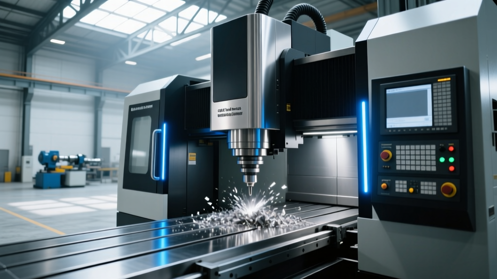
The CNC controller processes G-code into electrical signals for the servo drives. In modern vertical machining centers, the bottleneck is rarely the mechanical hardware, but the controller’s look-ahead capability and interpolation speed.
When machining complex 3D surfaces (such as injection mold cavities), the CAM software generates thousands of microscopic linear (G1) moves. Standard controllers process 200 blocks of look-ahead, which causes the machine to decelerate at sharp vector changes, resulting in dwell marks on the workpiece. Advanced systems like the Fanuc 30i-B or Siemens Sinumerik One utilize 1,000 to 5,000 blocks of look-ahead combined with jerk control (limiting the rate of change of acceleration). This smooths the velocity profile, allowing the VMC to maintain a constant feed rate of 5,000 mm/min through complex contours without sacrificing a Ra 0.4 µm surface finish.
Real-World Specifications: 2026 VMC Market Tiers
When specifying a CNC vertical machining center for a facility, buyers must align the machine’s kinematic capabilities with their specific part geometries and tolerances. Below is a technical breakdown of three distinct market tiers.
Tier 1: Entry-Level Job Shop (e.g., Haas VF-2SS)
- Price Range: $75,000 – $95,000
- Spindle: 12,000 RPM, Direct-Drive, CAT40
- Traverses: 30.5 m/min (X, Y, Z)
- Guideways: Linear roller bearings
- Use Case: General purpose job shop work, aluminum enclosures, basic steel fixtures. High ROI for low-complexity parts.
Tier 2: Mid-Range Production (e.g., DMG MORI CMX 600V)
- Price Range: $120,000 – $160,000
- Spindle: 15,000 RPM, Inline Direct-Drive, BT40 / HSK-A63
- Traverses: 36 m/min (X, Y, Z)
- Guideways: Heavy-duty linear rollers with integrated scale feedback
- Use Case: Automotive production, medical implants, continuous 24/7 lights-out manufacturing with pallet pools.
Tier 3: High-Precision Mold & Aero (e.g., Makino PS65)
- Price Range: $250,000+
- Spindle: 33,000 RPM, HSK-F63, Core-cooled
- Traverses: 20 m/min (Optimized for contouring, not rapid air-cutting)
- Guideways: Hand-scraped box ways or ultra-precision linear motors
- Use Case: Hard milling of H13 tool steel (60+ HRC), graphite EDM electrodes, tight-tolerance aerospace structural nodes.
Critical Failure Modes and Preventative Maintenance
Even the most rigid CNC vertical machining center will degrade if specific mechanical failure modes are ignored. Understanding these edge cases is vital for maintenance managers.
“The most common cause of scrapped parts on a VMC is not spindle runout, but way-lube starvation leading to stick-slip on the X and Y axes. If the metering units in the automatic lubrication system clog with oxidized oil, the axis will jerk during low-speed contouring, leaving visible chatter marks on the part.” — Senior Applications Engineer, Sandvik Coromant Technical Guide on Milling Kinematics.
1. Drawbar Belleville Spring Fatigue
The pneumatic cylinder that releases the tool relies on a stack of Belleville (conical) spring washers to clamp it. Over 500,000 tool changes, these springs lose their elastic memory. If the retention force drops below 2,000 lbf on a CAT40 taper, the tool holder will vibrate under heavy radial loads, causing severe chatter and premature spindle bearing failure. Action: Measure drawbar pull-force with a digital force gauge every 12 months.
2. Ball Screw Backlash and Reversal Errors
As ball nuts wear, the clearance between the ball bearings and the screw thread increases. This manifests as a reversal error when the axis changes direction (e.g., during circular interpolation of a bore). While CNC controllers can apply software backlash compensation, this only masks the issue and creates a "dead band" in the servo loop. Action: Perform a laser interferometer pitch-error and backlash mapping annually, and mechanically pre-load the ball nut if reversal error exceeds 0.005mm.
Summary: Specifying for the Application
Selecting the right CNC vertical machining center requires looking past the marketing brochures and analyzing the drive mechanics, spindle cooling architecture, and control interpolation limits. A C-frame machine with a 12,000 RPM belt-drive spindle is a highly profitable workhorse for general steel milling. However, if your shop is transitioning to 5-axis simultaneous aerospace work or hard-milling mold cores, investing in a bridge-type VMC with core-cooled direct-drive spindles and nano-interpolation controls is a non-negotiable requirement for holding micron-level volumetric tolerances.