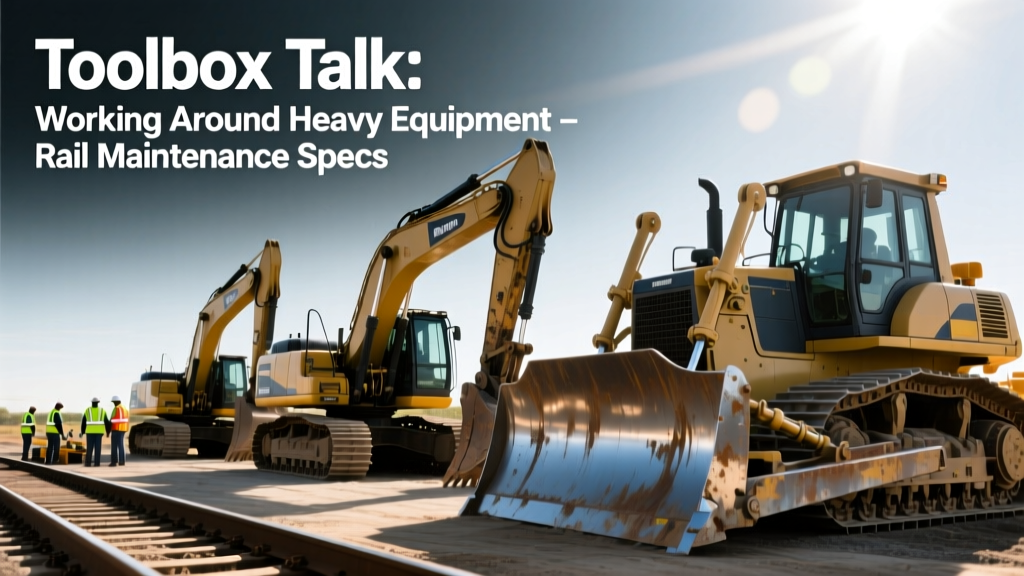
Toolbox Talk Working Around Heavy Equipment: Rail Maintenance Specs
Master your toolbox talk working around heavy equipment with technical specs, blind spot data, and hydraulic hazards of railroad maintenance machines.
When conducting a toolbox talk working around heavy equipment in a rail yard or on a mainline right-of-way, supervisors must move beyond generic safety platitudes. Railroad maintenance machinery operates under extreme hydraulic pressures, generates high-velocity debris, and features complex blind geometries that differ vastly from standard earthmoving equipment. To protect ground crews, safety officers must understand the exact technical specifications and mechanical behaviors of the machines they are working near.
This guide breaks down the operational mechanics, precise specifications, and specific hazard zones of primary railroad maintenance equipment, providing the technical depth required to run an effective, life-saving safety briefing.
The Mechanics of Track Tamping Machines
Track tampers consolidate the ballast beneath railroad ties to maintain track geometry. The industry standard, such as the Plasser & Theurer 09-3X Tamping Express, relies on high-frequency vibration and immense hydraulic squeezing force.
Technical Specifications & Operational Behavior
- Vibration Frequency: Tamping picks vibrate at approximately 35 Hz (2,100 RPM) to liquefy the crushed stone ballast.
- Squeezing Pressure: Hydraulic cylinders apply up to 150 kN (approx. 33,700 lbs) of squeezing force per pair of tamping picks.
- System Pressure: The main hydraulic pumps operate at 3,000 to 5,000 PSI to drive the squeeze cylinders and lifting hooks.
During a toolbox talk, explicitly warn crews about the tamping bank. If a hydraulic hose rated for 5,000 PSI ruptures near the tamping heads, the resulting fluid injection hazard can penetrate skin at distances up to 6 feet. Furthermore, the 35 Hz vibration frequently ejects sharp, angular ballast stones laterally at speeds exceeding 40 mph. Ground crews must maintain a strict 10-foot lateral exclusion zone while the tamping bank is engaged.
Ballast Cleaners and Undercutters
Undercutters remove fouled ballast from beneath the track structure. Machines like the Progress Rail RM-90 Ballast Cleaner are massive, continuous-operation excavators that fundamentally alter the ground conditions around them.
How the Excavating Chain Works
The RM-90 utilizes a heavy-duty excavating chain that runs beneath the track ties. The chain is driven by a hydraulic motor and pulls fouled ballast up to the screening tower. The cutting depth is typically adjustable between 6 to 14 inches below the bottom of the tie.
| Machine Component | Operating Specification | Ground Crew Hazard & Clearance |
|---|---|---|
| Excavating Chain | 6-8 ft/sec linear speed; 40,000 lbs tension | Catastrophic snap-back zone. Maintain 15 feet lateral clearance. |
| Screening Tower | Vibratory decks operating at 900 RPM | Overhead debris drop zone. Hard hats mandatory; no standing beneath. |
| Spoil Conveyor | Belt speed up to 400 ft/min; swings 90 degrees | Swing radius crush hazard. Barricade the conveyor slew ring. |
| Track Lifting Hooks | Lifts track grid up to 4 inches | Pinch points between tie and rail base. Never place hands near hooks. |
According to the Federal Railroad Administration (FRA) Roadway Worker Safety guidelines, establishing distinct limits of authority and physical barricades around continuous-motion machinery like undercutters is a primary defense against struck-by incidents.
Automated Spike Pullers and Fastening Systems
Modern track rehabilitation relies on automated fastening machines, such as the Pandrol Jackson Spike Puller. These machines automate the extraction of cut spikes or lag screws from the ties.
Extraction Mechanics and Ejection Risks
The machine uses hydraulic jaws to grip the spike head, applying a vertical pulling force that frequently exceeds 30,000 lbs per head. When a spike is rusted, bent, or embedded in hardened oak ties, the steel spike can shear under this immense tensile load.
💡 Toolbox Talk Framework: The "Shear-Line" ConceptTeach ground crews the concept of the "Shear-Line." When a spike puller exerts 30,000 lbs of force and the spike snaps, the top half of the spike becomes a high-velocity projectile. The shear-line is the 360-degree radius around the pulling head (typically 8 feet) where shrapnel can travel. Crews must never lean in to inspect a stuck spike while the hydraulic system is pressurized.
Blind Spot Geometry in Rail Maintenance Equipment
Unlike standard excavators that rotate 360 degrees on a turntable, most self-propelled railroad maintenance equipment operates on a fixed wheelbase with a unidirectional operator cab. This creates severe, asymmetric blind spots.
Mapping the Blind Zones
Consider a standard self-propelled rail grinder or a large tamper. The operator sits elevated, often 10 to 12 feet above the railhead, positioned behind a long engine hood or complex array of hydraulic control consoles.
- The Forward Plow Blind Spot: Machines equipped with front-mounted ballast plows or snow wedges create a forward blind spot extending 12 to 18 feet directly in front of the machine. A worker crouching to inspect a switch frog in this zone is entirely invisible to the operator.
- The Cab Pillar Obscuration: Heavy structural A-pillars in the cab, combined with external rear-view mirrors, can create vertical blind slices up to 3 feet wide at a distance of 20 feet from the machine.
- Nighttime Glare: Rail machines utilize high-lumen LED work lights (often 50,000+ lumens total output) to illuminate the track bed at night. If a ground worker approaches the operator's line of sight wearing improperly angled retro-reflective tape, the glare can temporarily blind the operator, masking the worker's presence.
The OSHA Struck-By Hazards guidelines emphasize that relying solely on operator vigilance is insufficient; engineering controls and strict proximity protocols must be enforced.
Integrating Telematics and UWB Proximity Detection
As of 2026, advanced railroad maintenance fleets are increasingly equipped with Ultra-Wideband (UWB) proximity detection systems. Unlike standard GPS or RFID, UWB provides centimeter-level accuracy in the complex metallic environment of a rail yard.
How UWB Protects Ground Crews
Workers wear UWB-enabled tags on their hard hats or high-visibility vests. The machine's onboard computer continuously maps the exact 3D position of every tagged worker relative to the machine's hydraulic swing radius and travel path.
- Zone 1 (Warning - 15 feet): Operator receives a visual dashboard alert; machine speed is automatically governed to 2 MPH.
- Zone 2 (Danger - 8 feet): Operator receives an audible cab alarm; hydraulic travel functions are restricted.
- Zone 3 (Critical - 3 feet): The machine's PLC (Programmable Logic Controller) triggers an automatic engine shutdown and dumps hydraulic pressure to the travel brakes.
During your safety briefing, verify that all crew tags are charged and synced to the specific machine's PLC before work commences. A UWB tag left in the crew truck provides zero protection.
Executing the Technical Briefing
A highly effective safety briefing on rail equipment requires translating these technical specifications into actionable rules. Use the following checklist to structure your next meeting:
- Identify Active Pressures: Explicitly state which hydraulic circuits will be pressurized (e.g., "The tamping bank will be running at 4,000 PSI today").
- Define the Exclusion Zones: Use physical barricades or high-visibility tape to mark the 15-foot undercutters chain snap-back zone and the 10-foot tamper ballast ejection zone.
- Verify Comms: Ensure all ground workers are on the same dedicated UHF radio channel as the machine operator, utilizing standardized rail terminology (e.g., "Shoving," "Point Protection").
- PPE Verification: Confirm Class 3 high-visibility apparel is clean (dirty retro-reflective tape loses up to 60% of its luminosity) and double hearing protection is worn (machines routinely exceed 95 dB(A) at the operator station and 85 dB(A) at 20 feet).
By anchoring your safety protocols in the actual mechanical realities and physical forces of railroad maintenance equipment, you transform a routine compliance exercise into a critical, life-saving technical briefing.