What CNC Machining Pictures Reveal When Buying Oil & Gas CNC Mills
Learn how to analyze CNC machining pictures to evaluate machine rigidity, surface finishes, and chip control when buying equipment for oil and gas components.
The Visual Audit: Why CNC Machining Pictures Matter for O&G Buyers
Purchasing CNC equipment for the oil and gas sector is a high-capital endeavor with zero margin for error. In 2026, a single heavy-duty 5-axis mill or multitasking lathe designed for API 6A wellhead components can easily exceed $1.4 million. While manufacturer brochures highlight spindle torque, rapid traverse rates, and axis travel, spec sheets rarely reveal how a machine handles the brutal interrupted cuts of a 4130 steel valve body or the work-hardening tendencies of Inconel 718. This is where analyzing cnc machining pictures becomes a critical, often overlooked, due diligence tool for equipment buyers and contract manufacturing selectors.
When evaluating potential machine tool investments, requesting high-resolution images of test cuts, setup configurations, and chip evacuation provides unfiltered data on machine rigidity, toolpath optimization, and thermal management. By training your engineering team to decode these visual cues, you can separate marketing claims from actual metallurgical capabilities before signing a purchase order.
Decoding Surface Finish Anomalies in Portfolios
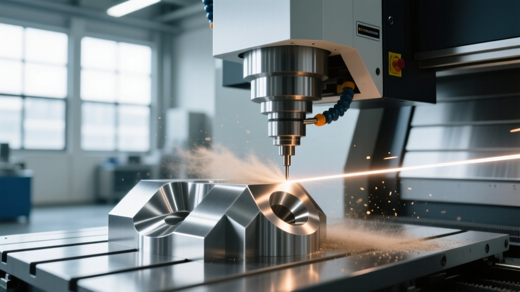
Oil and gas components are governed by strict sealing and pressure containment standards. Ring Type Joint (RTJ) flanges, for example, demand sealing grooves with a surface roughness of Ra 63 µin (1.6 µm) or better, as dictated by API specification standards. When reviewing cnc machining pictures of a machine builder's test samples or a contract shop's portfolio, look closely at the RTJ grooves and API flange faces.
- Microscopic Chatter Marks: If the pictures reveal uneven tool overlap or microscopic chatter lines inside the groove, the machine's spindle bearings or structural damping are inadequate for the low-speed, high-torque interrupted cuts required for heavy O&G alloys.
- Tool Deflection Shadows: In deep-bore valve bodies, look for dimensional tapering or shadow lines at the bottom of the cut. This indicates a lack of Z-axis rigidity or excessive toolholder overhang, which will cause catastrophic scrap rates in production.
- Thermal Discoloration: Blue or purple tinting on the edges of machined 17-4 PH stainless steel in the photos indicates poor heat evacuation. The machine likely lacks the high-pressure coolant throughput necessary to manage the thermal loads of precipitation-hardening steels.
Machine Rigidity Indicators Hidden in Setup Photos
Blowout preventers (BOPs) and large manifold blocks require massive depths of cut (DOC) to hog out material from solid forged billets. Brochures will list the machine's total mass, but cnc machining pictures of the actual cutting zone tell the real story about dynamic rigidity.
Buyer's Tip: Analyze the Toolholder OverhangZoom in on the spindle interface in the setup photos. If the machine requires extended-length toolholders or heavy use of reduction collets to reach deep pockets, the machine's Y-axis and Z-axis columns lack the necessary structural mass. For O&G milling, demand a machine with a native, short-overhang spindle nose and a direct-drive torque motor to maintain rigidity at the cutting edge.
Visual Defect to Machine Specification Matrix
| Visual Cue in Machining Pictures | Underlying Machine Deficit | Required O&G Equipment Spec |
|---|---|---|
| Chatter in RTJ Grooves | Low spindle torque / poor structural damping | Minimum 1,000 Nm continuous torque at low RPM |
| Stringy, Bird-nesting Chips | Inadequate coolant pressure / poor chip conveyor | 1,000+ PSI through-spindle coolant (TSC) system |
| Tapered Deep Bores | Z-axis column flex / thermal growth | Thermo-stable column design with active cooling |
| Burnished Surface Edges | Spindle runout / worn bearing preloads | Spindle runout < 3 µm at the gauge line |
Chip Morphology and Coolant Delivery in Action Shots
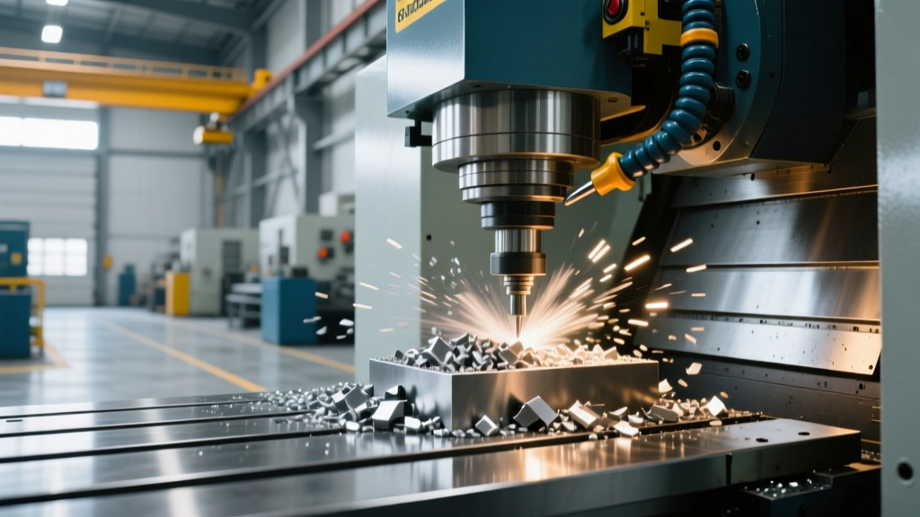
Machining corrosion-resistant alloys (CRAs) like Duplex 2205, Super Duplex 2507, and Inconel 718 is a staple of the oil and gas industry. These materials are notorious for work-hardening and generating immense cutting forces. When evaluating cnc machining pictures that capture the machine in mid-cycle, chip morphology is your best indicator of the machine's coolant delivery system and programming capability.
According to metallurgical machining guidelines from Okuma's oil and gas manufacturing resources, proper chip control in tough CRAs requires high-pressure coolant directed exactly at the shear zone. If the action shots show long, stringy chips wrapping around the toolholder or workpiece, the machine's standard 300 PSI coolant pump is wholly insufficient. For automated O&G production, you must specify a machine equipped with a 1,000 to 1,500 PSI variable-displacement piston pump and programmable coolant nozzles to break chips into manageable '9' shapes and prevent recutting, which destroys tool life and compromises NACE MR0175 surface integrity.
NACE MR0175 / ISO 15156 Compliance Warning:Surface integrity is non-negotiable in sour gas (H2S) environments. Micro-cracks or excessive smearing visible in magnified cnc machining pictures of test cuts can indicate severe thermal stress and plastic deformation during milling. These surface defects act as stress concentrators, leading to premature sulfide stress cracking (SSC) in the field. Always demand magnified visual proof of surface grain flow from the equipment builder.
Top-Tier CNC Platforms for Heavy-Duty O&G Alloys in 2026
If your visual audit confirms the need for extreme rigidity, high-torque spindles, and advanced chip evacuation, standard vertical machining centers will not suffice. Based on current market performance and visual portfolio audits, the following multitasking and 5-axis platforms represent the benchmark for O&G component manufacturing in 2026.
Mazak Integrex e-1600V/8
Designed specifically for large, heavy oilfield components like valve bodies and wellhead housings. The Integrex e-Series features a massive bed structure that eliminates the visual chatter marks often seen in lighter machines when performing heavy interrupted milling on 4130 and 8630 alloy steels. Expect capital expenditures between $1.3M and $1.6M depending on the integrated automation and high-pressure coolant packages.
DMG MORI NTX 3000
A powerhouse for long, complex shafts and downhole tooling. The NTX 3000's direct-drive torque motors and advanced thermal shielding ensure that deep-bore visual inspections reveal zero tapering, even during 12-hour continuous cycles. Its integrated CELOS control system allows for real-time monitoring, ensuring that the surface finishes seen in initial test pictures are perfectly replicated in high-volume production.
"In the oil and gas sector, you aren't just buying a machine; you are buying the ability to hold a 32-microinch finish on a 500-pound Inconel valve body without inducing residual tensile stress. The spec sheet tells you what the machine can do in a vacuum; the machining pictures tell you what it actually does under load." — Senior Manufacturing Engineer, Tier 1 O&G Contract Machine Shop
Frequently Asked Questions (FAQ)
What specific camera angles should I request in CNC machining pictures?
Request macro-lens shots of the cutting edge engaging the workpiece (to assess tool deflection), close-ups of the finished surface texture under directional lighting (to highlight chatter or smearing), and wide shots of the chip conveyor during heavy roughing cycles (to evaluate chip volume handling and coolant wash-down effectiveness).
Can cnc machining pictures reveal thermal growth issues?
Yes. If sequential pictures of a long downhole tooling shaft show slight dimensional tapering or surface finish degradation from the top of the part to the bottom, it strongly indicates that the machine's column and spindle are experiencing uncompensated thermal growth during the cycle.
Why do API 6A components require such strict visual surface audits?
API 6A wellhead and Christmas tree equipment operates under extreme pressures and often in corrosive environments. Any visual anomaly in the machining pictures—such as tool marks in a sealing area or smearing on a bearing journal—can lead to catastrophic pressure leaks or fatigue failures in the field, resulting in massive liability and environmental damage.