Next-Gen CNC Machining Projects: Surface Finish & Tolerance Tech
Discover how AI metrology and advanced tooling are redefining surface finish and tolerance standards for complex CNC machining projects in 2026.
The Paradigm Shift: From Post-Process to In-Process Metrology
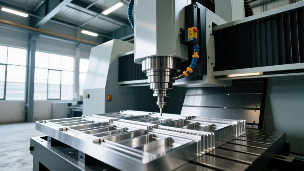
The execution of high-precision CNC machining projects has fundamentally evolved. The historical workflow—machine a part, remove it from the fixture, and inspect it on a Coordinate Measuring Machine (CMM)—is now considered a bottleneck in advanced manufacturing. In 2026, the industry standard for tight-tolerance components relies on closed-loop, in-process metrology. By integrating multi-sensor probing directly into the CNC work envelope, manufacturers are achieving sub-micron tolerances without breaking the primary setup.
Modern 5-axis machining centers, equipped with controllers like the Heidenhain TNC7 or Siemens Sinumerik One, utilize dynamic state monitoring to compensate for thermal drift, tool wear, and spindle displacement in real-time. This technological leap means that the limiting factor in CNC machining projects is no longer the machine's mechanical rigidity, but the software's ability to interpret and react to in-process data.
WARNING: The Hidden Cost of Over-TolerancingDesign engineers frequently apply blanket ±0.0005" tolerances to non-critical features, exponentially driving up part costs without adding functional value. Review the cost multipliers below before finalizing your CAD models:
- ±0.010" (Standard Milling): 1.0x baseline cost. Achieved with standard end mills and minimal probing.
- ±0.005" (Precision Milling): 1.2x cost. Requires premium carbide tooling and standard touch-probe cycles.
- ±0.001" (High Precision): 1.8x cost. Mandates thermal compensation, reduced depth-of-cut, and CMM verification.
- ±0.0005" (Ultra-Precision): 3.5x cost. Requires climate-controlled environments (±1°C) and non-contact laser tool setting.
- ±0.0001" (Sub-Micron): 8.0x+ cost. Exceeds standard CNC milling capabilities; necessitates secondary jig grinding or honing operations.
Redefining Standards: ASME Y14.5 and ISO 21920 in the Digital Thread
Executing complex CNC machining projects requires strict adherence to modern geometric dimensioning and tolerancing (GD&T) frameworks. The ASME Y14.5 standard remains the definitive guide for North American manufacturing, but its practical application has changed. With the widespread adoption of Model-Based Definition (MBD), tolerances are no longer read from 2D PDF drawings. Instead, Product and Manufacturing Information (PMI) is embedded directly into the 3D STEP AP242 CAD model.
CAM software in 2026 reads this PMI natively, automatically generating the appropriate probing cycles and toolpath containment boundaries. Similarly, the ISO 21920 surface texture specifications have shifted focus from simple Ra (Roughness Average) to more comprehensive parameters like Rz (Maximum Height of Profile) and Rsk (Skewness). For hydraulic valve spools or aerospace bearing races, a negative Rsk value—indicating a surface with deep valleys and flattened peaks—is critical for oil retention, even if the Ra value appears identical to a less functional surface.
Achieving Sub-Micron Surface Finishes (Ra < 0.1 µm)
When CNC machining projects demand optical-grade or frictionless surfaces, standard carbide tooling reaches its physical limits. Achieving an Ra below 0.1 µm (4 µin) directly off the machine requires a synthesis of ultrasonic technology, specialized tool geometries, and extreme coolant pressures.
Ultrasonic Assisted Machining (UAM)
For hardened steels (>50 HRC), ceramics, and titanium alloys, Ultrasonic Assisted Machining superimposes high-frequency, low-amplitude vibrations (typically 20-40 kHz) onto the cutting tool. This intermittent cutting action drastically reduces cutting forces and friction, eliminating the built-up edge (BUE) that typically destroys surface finishes in hard materials. UAM enables direct milling of D2 tool steel to an Ra of 0.2 µm, bypassing the need for secondary EDM or grinding operations.
Wiper Geometry and High-Pressure Coolant
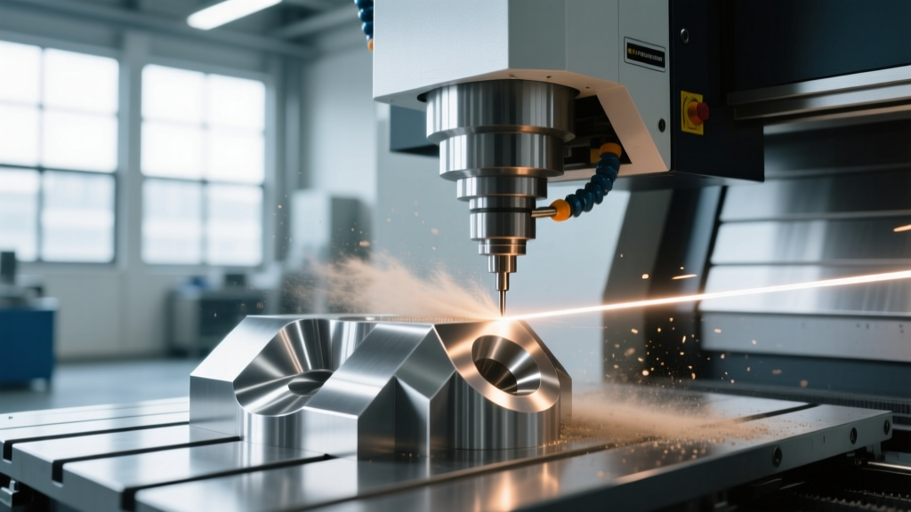
In softer materials like 6061-T6 aluminum or 316L stainless steel, wiper inserts are the key to mirror finishes. A wiper insert features a secondary, flatter cutting edge trailing the primary nose radius. This secondary edge 'wipes' the surface clean of the scallops left by the primary cutting edge, effectively doubling the feed rate while maintaining the same theoretical surface roughness.
However, wiper inserts generate immense heat and require flawless chip evacuation. If a chip is re-cut, the surface finish is instantly compromised. Modern CNC machining projects solve this by utilizing 1,000 to 1,500 PSI through-tool coolant delivery. This pressure shears the chip at the shear zone and flushes it from the cutting envelope before the next revolution of the spindle.
| Target Ra (µm) | Primary Process | Required Tooling / Tech | Typical Application |
|---|---|---|---|
| 3.2 - 1.6 | Standard End Milling | Standard 3-flute carbide, flood coolant | Structural brackets, enclosures |
| 0.8 - 0.4 | Fine Milling / Turning | Wiper inserts, high-speed spindles (20k+ RPM) | Automotive sealing surfaces, mold bases |
| 0.2 - 0.1 | Ultrasonic / Diamond Turning | PCD tooling, UAM spindles, 1000+ PSI coolant | Optical housings, aerospace bearing races |
| < 0.05 | Magnetic Abrasive Finishing | MAF post-process, specialized media | Medical implants, semiconductor valves |
Thermal Growth Compensation in Sub-Micron Tolerancing
When CNC machining projects demand tolerances tighter than ±0.0002", the primary enemy is no longer tool deflection; it is thermal expansion. A standard cast-iron machine spindle can grow up to 0.0015" axially during the first two hours of operation as bearings heat up. In 2026, high-end machining centers mitigate this through a combination of hardware and software innovations.
- Polymer Concrete Castings: Machines like the Röders RXP series utilize polymer concrete (reactive resin) beds instead of cast iron. This material offers 6 to 10 times the damping capacity of iron and significantly lower thermal conductivity, isolating the workpiece from ambient temperature fluctuations.
- Coolant Temperature Control: The cutting fluid is not just for lubrication; it acts as a thermal regulator. Advanced chillers maintain the coolant temperature to within ±0.1°C of the ambient room temperature, ensuring the workpiece and machine remain in thermal equilibrium.
- AI-Driven Spindle Mapping: Controllers now use machine learning algorithms trained on thousands of thermal cycles. By monitoring spindle load, RPM, and ambient sensors, the CNC predicts Z-axis thermal growth and applies micro-offsets via G-code macros (e.g., G10 L2 P1 Z-0.0003) dynamically throughout the cycle.
'The integration of digital twins with in-machine probing has effectively turned the CNC mill into its own metrology lab. We no longer inspect parts to find errors; we inspect the process to prevent them from occurring in the first place.'
— Dr. Aris Thorne, Director of Advanced Manufacturing Metrology, 2026 Industry Symposium
Toolpath Strategies for Tolerance Holding
Even with perfect metrology and thermal stability, the physical forces of cutting can push a part out of tolerance. Clamping forces and residual stresses in the raw material cause parts to warp the moment they are unclamped. Modern CAM systems address this through specialized toolpath strategies designed specifically for high-precision CNC machining projects.
Trochoidal Milling and Peel Milling: These adaptive toolpaths maintain a constant radial engagement angle and constant chip thickness. By avoiding sudden changes in cutting forces, the tool is less likely to deflect, and the workpiece experiences minimal localized stress. This is critical when machining thin-walled aerospace components from billet, where traditional zig-zag pocketing would induce enough residual stress to warp the wall by 0.005" upon unclamping.
Rest Roughing and Semi-Finishing: To hold tight geometric tolerances (like true position within 0.001"), the finishing pass must remove a perfectly uniform amount of material. If a finishing end mill encounters a 'rest' area of excess stock left by a larger roughing tool, the sudden spike in cutting force will deflect the tool, ruining the tolerance and the surface finish. Advanced CAM algorithms calculate exact rest material volumes and deploy smaller tools to semi-finish these specific zones before the final contour pass, ensuring the finishing tool experiences zero variation in radial load.