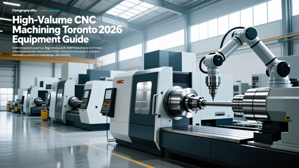
CNC Machining Prototyping vs Production: An Operator Guide
Master the shift from CNC machining prototyping to full production. Learn operator best practices, setup tweaks, and toolpath strategies for 2026.
The Core Divergence: Flexibility vs. Predictability
The transition from CNC machining prototyping to high-volume production is not merely a matter of increasing the part count on the machine control. It requires a fundamental shift in the operator’s mindset, toolpath strategy, and metrology protocols. In a prototyping environment, the primary objective is speed-to-model and geometric flexibility. Operators frequently adjust offsets on the fly, swap tooling mid-cycle to accommodate design changes, and prioritize getting a single complex geometry out of the vise over long-term tool life. Production machining, conversely, demands absolute predictability. The goal shifts to minimizing cycle time, ensuring thermal stability, and guaranteeing that the 5,000th part matches the 1st part within a tolerance band of ±0.0002 inches. Failing to adapt your operational strategy when scaling up is the leading cause of scrapped batches and blown tooling budgets in modern machine shops.
⚠️ The First Article Trap: Do not assume that a successful First Article Inspection (FAI) on a prototype run validates the process for mass production. Prototype runs often mask underlying issues like excessive tool deflection, poor chip evacuation, and thermal growth because the machine has time to cool between cycles. Production runs expose these flaws rapidly.Toolpath Optimization: Abandoning the 'Quick Cut' Mentality
During CNC machining prototyping, operators and programmers often rely on standard contouring, heavy stepovers, and conservative axial depths of cut (DOC) to quickly clear material without worrying about cycle time. When moving to production, this approach will destroy your profit margins and your spindle bearings. High-efficiency milling (HEM) techniques, such as Adaptive Clearing in Fusion 360 or Dynamic Motion in Mastercam, become mandatory.
Radial vs. Axial Engagement in Aluminum
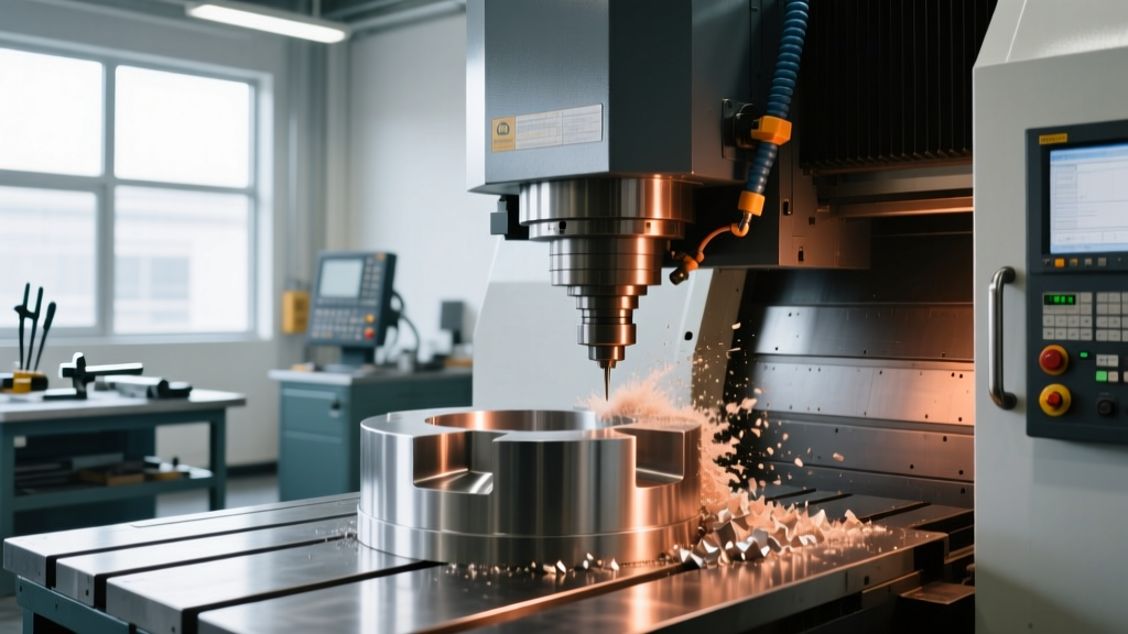
Consider a standard 1/2-inch diameter, 3-flute carbide end mill cutting 6061-T6 aluminum. In a prototype run, an operator might program a 0.125-inch DOC (25% of diameter) with a 50% radial stepover, running at 8,000 RPM and 60 IPM. This works fine for a one-off. In production, that same toolpath generates excessive heat and uneven flank wear. The production optimization requires flipping the engagement ratio: increase the axial DOC to 1.0 inch (200% of diameter) while dropping the radial stepover to 5% (0.025 inches). By maintaining a constant, low radial engagement, the tool cuts cooler, chips are evacuated instantly, and you can push the spindle to 14,000 RPM and 350 IPM. This reduces cycle time by up to 40% and extends tool life by a factor of three, according to Sandvik Coromant's machining guidelines.
💡 Operator Tip: Implement Sister ToolingNever run a production batch without programming sister tooling in your Fanuc or Haas control. If Tool #4 (roughing end mill) reaches its programmed life limit of 120 minutes or 400 parts, the control will automatically call Tool #14 (the sister tool) without stopping the cycle. Set the life limit at 80% of the tool's actual failure point to ensure you never cut with a dull edge, which causes work hardening and subsequent tapping failures.
Workholding Evolution: From Manual Clamping to Automated Fixturing
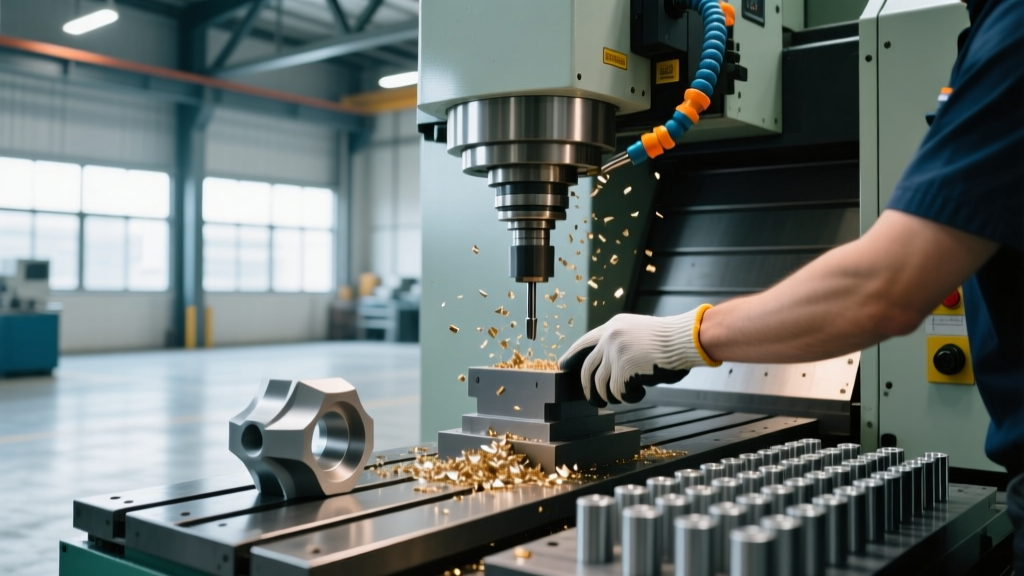
The workholding used in CNC machining prototyping is almost always modular and manual. A standard 6-inch Kurt DX6 vise with aluminum soft jaws machined on the fly is the industry standard for getting a prototype done in an afternoon. However, manual vises introduce operator-dependent variables. The torque applied to the vise handle varies between operators, leading to part distortion, especially in thin-walled components or engineering plastics like Delrin and PEEK.
Production Workholding Matrix
| Parameter | Prototyping Setup | Production Setup |
|---|---|---|
| Primary Hardware | Manual Kurt Vise / Toe Clamps | Pneumatic/Hydraulic Fixtures, SMW-AUTOBLOK Chucks |
| Jaw / Fixture Cost | $50 - $150 (Soft jaws) | $3,500 - $15,000+ (Custom tombstones/valves) |
| Load/Unload Time | 45 - 90 seconds (Manual torque) | 3 - 8 seconds (Push-button actuation) |
| Repeatability | ±0.001" (Operator dependent) | ±0.0002" (Mechanically locked) |
| Multi-Part Capacity | 1 part per cycle | 4 to 16+ parts per cycle (Pallet systems) |
For production runs exceeding 500 parts, the capital expenditure of custom hydraulic fixturing or pneumatic tombstones pays for itself purely through load/unload time reduction and the elimination of clamping distortion. Furthermore, production fixturing allows for aggressive toolpath entry and exit moves that would otherwise vibrate a part out of a manual vise.
In-Process Metrology: Closing the Feedback Loop
Prototyping relies heavily on post-process inspection. The operator machines the part, removes it from the machine, cleans it, and measures it on a manual CMM or with micrometers at the inspection bench. If a bore is 0.0005 inches undersized, the operator adjusts the tool wear offset and cuts the next part. This stop-and-measure rhythm is entirely unviable for production machining.
Implementing Renishaw OMP600 Probe Cycles
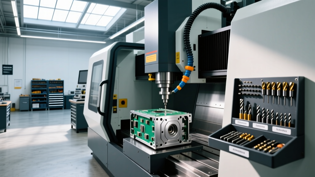
Production environments require in-machine metrology to create a closed-loop feedback system. Utilizing a high-accuracy touch probe, such as the Renishaw OMP600 series, allows the machine to inspect critical features immediately after machining them, while the part is still clamped and thermally stable. Operators must program probing routines that not only verify dimensions but automatically update macro variables to adjust tool offsets on the fly. For example, if the probe measures a turned diameter at 2.0003 inches (where nominal is 2.0000), the control’s macro logic should automatically subtract 0.0003 from the finish tool’s geometry offset before the next part begins. This eliminates human error in offset calculation and prevents the 'scrap-two-parts-while-dialing-in' syndrome that plagues manual setups.
'The most expensive mistake an operator can make in production is assuming the machine's thermal state at 8:00 AM is identical to its state at 2:00 PM. In-machine probing compensates for thermal growth in the ballscrews and spindle housing that manual offline inspection completely misses.'
The Operator’s Handoff Checklist: Prototyping to Production
Before an operator green-lights a transition from a validated prototype to a continuous production run, the following technical audit must be completed on the shop floor:
- Chip Evacuation Verification: Run the roughing cycle with the machine doors open and observe chip flow. If chips are recutting or wrapping around the tool (especially with stringy materials like 304 Stainless or Titanium), the toolpath must be revised. Recutting chips in production will cause catastrophic tool failure within the first 50 parts. Consult OSG's tooling knowledge center for specific chip-breaker geometries if issues persist.
- Coolant Pressure & Nozzle Alignment: Prototyping often gets away with standard flood coolant. Production requires high-pressure through-spindle coolant (TSC) at 300+ PSI for deep cavity milling to ensure chips are evacuated from the cutting zone. Verify all programmable coolant nozzles are physically aimed at the tool tip at the exact Z-depth of the cut.
- Thermal Stabilization Run: Execute a 15-minute dry-run cycle with the spindle at maximum programmed RPM and rapid traverse rates. This pre-loads the spindle bearings and expands the ballscrews to their operating temperature before the first production part is cut, ensuring the first part matches the fiftieth part.
- Deburring Integration: Identify opportunities to machine chamfers and break edges directly on the CNC mill using lollipop end mills or chamfer mills. Relying on manual deburring for 10,000 parts introduces a massive secondary bottleneck and inconsistent edge breaks.
- Control Program Lock: Once the FAI is approved and offsets are finalized, lock the G-code program in the control directory. Operators should only have permission to adjust wear offsets (typically limited to a ±0.005" guard band), preventing accidental overwrites to the core toolpath logic.