Optimizing Your CNC Machining Machine for Tight-Tolerance Enclosures
Learn how to configure a CNC machining machine for tight-tolerance electronics enclosures. Includes tooling matrices, case studies, and EMI tips.
The Hidden Geometry of Electronics Enclosures
Manufacturing enclosures for aerospace avionics, medical imaging, and high-frequency telecommunications requires far more than simply hollowing out a block of aluminum. These components serve as the primary defense against electromagnetic interference (EMI), environmental ingress (IP67/IP68), and thermal throttling. When configuring a CNC machining machine for these applications, the challenge lies in holding true position tolerances of ±0.0005 inches across complex 3D mating surfaces while maintaining surface finishes of 32 Ra or better.
Standard 3-axis vertical machining centers (VMCs) often fall short due to the need for multiple setups, which introduce cumulative stacking errors. Transitioning to a 5-axis workflow minimizes part handling, but it demands rigorous attention to machine thermals, tool deflection, and advanced workholding strategies.
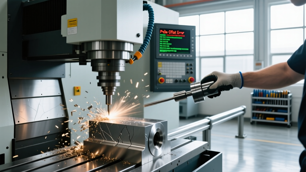
Warning: Material-Specific Thermal ExpansionWhen machining AZ91D magnesium enclosures for lightweight aerospace applications, remember that magnesium's coefficient of thermal expansion is roughly 20% higher than 6061-T6 aluminum. Parts measured immediately after being unclamped from a warm fixture will shrink past the lower tolerance limit once they reach the 68°F (20°C) metrology lab temperature. Always enforce a 45-minute thermal soak time before CMM inspection to avoid false rejections.
Case Study: 5-Axis Workflow for Avionics Bulkheads
Consider the production of a 14x10 inch avionics enclosure machined from 6061-T6 aluminum. The part features deep internal pockets for PCB stacking, thin walls (0.060 inches) for weight reduction, and a perimeter O-ring gland requiring a surface finish of 16 Ra to prevent seal extrusion under pressure.
Workholding and Fixture Design
Clamping force is the enemy of thin-walled enclosures. A standard 6-inch Kurt vise applying 4,000 lbs of clamping force will easily distort a 0.060-inch wall by up to 0.003 inches. Once unclamped, the wall springs back, ruining the flatness of the mating surface. To counteract this, top-tier machine shops utilize custom machined tombstones with low-profile strap clamps and adjustable support pins. By distributing the clamping force across the Z-axis datum rather than squeezing the X/Y perimeter, distortion is reduced to less than 0.0002 inches.
Toolpath Strategy and Chip Evacuation
Deep pocketing in electronics enclosures traps chips, leading to recutting and localized work hardening. While Minimum Quantity Lubrication (MQL) is popular for environmental reasons, high-pressure through-spindle coolant (TSC) at 1,000 PSI remains the superior choice for deep-cavity enclosure machining. The kinetic energy of the coolant stream fractures the chip and clears the cutting zone, which is critical when using long-reach tooling.
Tooling Matrix for 0.0005-Inch Tolerances
Selecting the correct cutting tool geometry is non-negotiable. Standard 2-flute end mills designed for general-purpose aluminum machining will leave chatter marks on thin walls and fail to hold tight profile tolerances. According to tooling data published by Sandvik Coromant, utilizing variable helix angles disrupts harmonic resonance, effectively eliminating chatter on thin-walled features.
| Feature Type | Tool Diameter | Flute Count / Helix | Coating | Spindle Speed (RPM) | Feed Rate (IPM) |
|---|---|---|---|---|---|
| Roughing Pockets | 1/2" (12.7mm) | 3-Flute / 45° Variable | ZrN (Zirconium Nitride) | 14,000 | 160 |
| Thin Wall Finishing | 1/4" (6.35mm) | 3-Flute / 60° High Helix | Uncoated Polished Carbide | 18,000 | 95 |
| O-Ring Gland Floor | 1/8" (3.17mm) | 2-Flute / Ball Nose | TiB2 (Titanium Diboride) | 22,000 | 40 |
| EMI Groove Profiling | 0.040" (1.01mm) | 2-Flute / Stub Length | Uncoated Micro-Grain | 35,000 | 12 |
Overcoming EMI/RFI Shielding Groove Tolerances
Conductive elastomer gaskets, such as those specified by Parker Chomerics, require a precise knife-edge groove to ensure proper compression and continuous EMI shielding. A standard groove might be 0.040 inches wide and 0.030 inches deep. Machining this with a standard end mill on a conventional CNC machining machine often results in tool deflection, bell-mouthing the groove and causing RF leakage at high frequencies.
To achieve the required straight-wall profile, machinists must utilize specialized miniature end mills. Suppliers like Harvey Tool offer micro-end mills with reinforced cores and stub lengths specifically designed to minimize deflection in micro-grooving applications. Running these tools at 35,000 RPM requires a machine equipped with high-frequency spindles and ultra-precise linear glass scales to maintain true position within 0.0002 inches.
Thermal growth in the Z-axis is the silent killer of tight-tolerance enclosure machining. Even a 2-degree Fahrenheit shift in the shop environment can push a 15,000 RPM spindle out of the 0.0005-inch tolerance band required for IP68 sealing surfaces. Machine thermal compensation software is no longer optional; it is a baseline requirement.
— Lead Manufacturing Engineer, Aerospace Avionics Division
Metrology: Validating IP68 and True Position
You cannot machine what you cannot measure. Verifying the flatness of an enclosure mating surface and the true position of bulkhead connector holes requires a multi-tiered metrology approach. According to guidelines from NIST Advanced Manufacturing, relying solely on contact-based probing can miss microscopic surface anomalies that compromise environmental seals.
- Phase 1: In-Process Probing. Use a Renishaw OMP60 spindle probe to verify datum shifts and roughing stock allowances immediately after the part is flipped to the second operation.
- Phase 2: Vision Measuring Machines (VMM). Utilize non-contact optical scanning to map the 0.040-inch EMI grooves. Contact probes will drag and deform the soft conductive gasket material if used for final inspection.
- Phase 3: CMM Flatness Mapping. Deploy a Zeiss CONTURA CMM with a VAST XXT scanning probe head to take 5,000+ data points across the 14-inch mating perimeter, ensuring form error does not exceed 0.0003 inches.
Sourcing and Machine Selection Criteria for 2026
Selecting the right CNC machining machine requires evaluating more than just axis travel. For tight-tolerance electronics enclosures, the machine's structural rigidity, thermal stability, and control processing speed dictate the scrap rate.
As of early 2026, a fully optioned 5-axis VMC capable of this work—such as the Haas UMC-500SS or the DMG MORI DMU 50 3rd Gen—lists between $195,000 and $260,000. When building the business case for this capital expenditure, factor in the cost of secondary operations. A 3-axis machine might cost $90,000, but the labor, fixturing, and cumulative scrap generated by three separate setups for a complex avionics enclosure will erase the savings within the first 1,000 parts.
Key Machine Specifications to Demand:
- Direct-Drive Torque Motors: Eliminate backlash associated with worm-gear rotary tables, ensuring true position accuracy on radial connector patterns.
- Linear Glass Scales: Mandatory on all linear axes to bypass ball-screw thermal expansion errors during long, continuous roughing cycles.
- High-Pressure Coolant (1,000+ PSI): Essential for chip evacuation in deep PCB cavities and extending the life of micro-drills used for RF shielding via holes.
- Thermal Spindle Compensation: Software that dynamically adjusts the Z-axis zero offset based on real-time spindle temperature sensors.
Ultimately, producing tight-tolerance electronics enclosures is an exercise in controlling variables. By marrying advanced 5-axis kinematics with specialized micro-tooling and rigorous thermal management protocols, contract machine shops can reliably deliver the precision that modern aerospace and medical electronics demand.