Operator Training for CNC Machining Aerospace Parts: Best Practices
Master CNC machining aerospace parts with expert operator training. Learn AS9100 compliance, titanium milling tactics, and precision tooling protocols.
The Reality of Aerospace CNC Machining: Beyond Basic G-Code
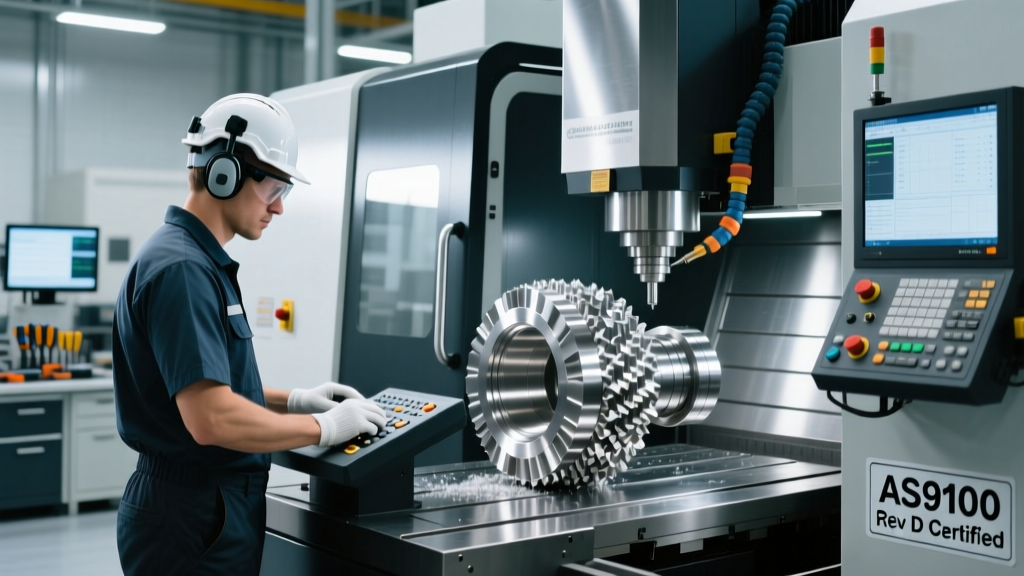
CNC machining aerospace parts demands a fundamentally different operational mindset than commercial or automotive manufacturing. When machining critical flight components—such as titanium landing gear actuators or Inconel turbine blisks—the cost of a scrapped part extends far beyond raw material waste. A single non-conformance can trigger an AS9100 Rev D corrective action report, halt an entire assembly line, and compromise flight safety. Operator training in this sector must pivot from simple machine operation to comprehensive process control, metallurgical awareness, and rigorous metrological verification.
According to Modern Machine Shop's aerospace manufacturing coverage, the industry is rapidly shifting toward 5-axis simultaneous machining and digital twin integration, requiring operators to understand complex kinematics and thermal displacement models, not just tool offsets.
Warning: The Cost of Non-ConformanceIn aerospace CNC machining, a $50 endmill failure on a $15,000 forged titanium bulkhead doesn't just cost the part. It triggers an 8D problem-solving process, halts downstream assembly, and damages supplier scorecards. Operators must be trained to recognize acoustic and visual cues of tool degradation before catastrophic failure occurs.
AS9100 Rev D and the Traceability Mindset
The SAE International AS9100 Rev D standard mandates strict configuration management and traceability. Operator training must embed these requirements into daily muscle memory.
- Material Certification Verification: Before loading a billet, operators must cross-reference the physical heat lot number stamped on the material with the ERP system's digital certificate of conformity (CoC).
- First Article Inspection (FAI): Operators must understand AS9102 FAI requirements. This means machining the first part, halting production, and collaborating with CMM (Coordinate Measuring Machine) programmers to verify 100% of the drawing dimensions before running the batch.
- Tool Life Management: Aerospace contracts often mandate maximum tool life limits. If a CAM program dictates a 120-minute tool life for a roughing endmill, the operator must log the exact cutting time and discard or regrind the tool at 110 minutes, regardless of visual edge wear.
Material-Specific Operator Protocols
Aerospace alloys are engineered to withstand extreme environments, making them notoriously hostile to cutting tools. Operators must be trained on the specific failure modes of these materials.
Titanium (Ti-6Al-4V) Milling Tactics
Titanium's low thermal conductivity means 80% of the heat generated during cutting remains in the chip and the cutting edge, rather than dissipating into the workpiece. Operators must be trained to utilize high-pressure through-tool coolant systems (minimum 1,000 PSI) to fracture chips and prevent chip welding (built-up edge). When performing trochoidal milling on deep aerospace pockets, operators must monitor the spindle load meter; a sudden 5% spike in load indicates work hardening or chip recutting, requiring an immediate feed rate override adjustment.
Inconel 718 Turning and Milling Strategies
Inconel 718 work-hardens rapidly beneath the cut. The golden rule for operators machining nickel-based superalloys is never let the tool dwell. If a spindle stop or feed hold is required, the tool must be retracted from the cut first. Dwelling for even two seconds will create a hardened glaze on the part surface that will instantly shatter the carbide insert upon re-engagement. Operators should also be trained to use variable helix, variable pitch endmills (such as the Destiny Viper series) to disrupt harmonic frequencies and eliminate chatter in thin-walled aerospace structures.
Cutting Parameters and Tool Life Expectancy Matrix
The following matrix serves as a baseline training reference for operators setting up new aerospace jobs. These parameters assume rigid CNC platforms (e.g., Makino a61nx or DMG MORI DMU 50 3rd Generation) with high-pressure coolant.
| Material | Hardness | Cutting Speed (SFM) | Feed/Tooth (in) | Coolant Pressure |
|---|---|---|---|---|
| Ti-6Al-4V (Annealed) | 32 HRC | 120 - 150 | 0.004 - 0.006 | 1,000+ PSI (Through-Tool) |
| Inconel 718 (Aged) | 40 HRC | 80 - 100 | 0.003 - 0.005 | 700+ PSI (Through-Tool) |
| Al 7075-T6 | 150 HB | 1,200 - 1,500 | 0.008 - 0.012 | Flood / MQL |
| 17-4 PH Stainless | 33 HRC | 150 - 180 | 0.005 - 0.007 | 300 PSI (Flood) |
Advanced Metrology and Thermal Compensation
Machining aerospace parts to tolerances of ±0.0002 inches (5 microns) requires operators to act as metrologists. The NIST Advanced Manufacturing Portal frequently highlights thermal growth as the primary enemy of tight-tolerance machining.
Best Practice: The 15-Minute Spindle Warm-UpOperators must execute a standardized spindle warm-up cycle at the start of every shift and after any idle period exceeding two hours. Running the spindle at 8,000 RPM for 15 minutes stabilizes the ceramic bearing grease and expands the spindle housing to its operational thermal equilibrium. Skipping this step can result in Z-axis thermal growth of up to 0.0015 inches, instantly scraping a tight-tolerance aerospace bore.
Furthermore, operators must be proficient in running in-process probing routines. Using systems like the Renishaw OMP60 or Blum Micro Compact, operators should program and execute mid-cycle probe routines to update work offsets dynamically. This compensates for tool wear and minor part deflection during heavy roughing passes before the finishing tools are deployed.
5-Axis Kinematics and Tool Center Point (TCP) Calibration
For complex aerospace geometries like impellers and structural airfoils, 5-axis simultaneous machining is mandatory. Operators must be trained to verify the machine's kinematic chain. Over time, the physical centerlines of the rotary tables (B and C axes) drift due to thermal expansion and mechanical wear.
Operators should run a TCP (Tool Center Point) calibration cycle using a calibration sphere and a tool-mounted probe at the beginning of every critical setup. If the kinematic error exceeds 0.0005 inches, the operator must update the machine's kinematic compensation parameters (e.g., Fanuc's G43.4 TCP variables or Siemens TRAORI settings) to ensure the tool tip remains perfectly perpendicular to the complex surface contours.
Toolholding: Shrink Fit vs. Hydraulic for Finishing Passes
Toolholding selection directly impacts surface finish and dimensional accuracy. While hydraulic chucks offer excellent damping for roughing titanium, they lack the necessary rigidity for finishing thin-walled aerospace aluminum structures. Operators must be trained to utilize induction shrink-fit toolholders (such as those from Haimer or Zoller) for all finishing operations. Shrink-fit holders guarantee a concentricity and runout of less than 3 microns (0.0001 inches), which is critical for maintaining the exact step-over required to achieve a 32 Ra micro-inch surface finish on aerodynamic surfaces.
"In aerospace machining, the toolholder is not just a clamping device; it is the final link in the precision chain. A $300 endmill running in a collet chuck with 0.001" runout will perform worse than a $50 endmill in a shrink-fit holder with 0.0001" runout."
Standard Operating Procedure (SOP): Shift Handoff Protocol
Aerospace machining operations rarely fit into a single 8-hour shift. Incomplete setups and poor communication during shift changes are primary drivers of scrap. Operators must follow this strict handoff protocol:
- Machine State Documentation: Record the exact line of G-code where the machine stopped. Note any active tool length or work offsets that were manually tweaked during the run.
- Tool Life Status: Physically inspect and document the remaining tool life percentage for all active roughing and finishing tools in the magazine.
- Coolant and Chip Management: Verify coolant concentration (maintain 8-10% for aerospace alloys to prevent bacterial growth and corrosion). Clear all titanium or magnesium chips from the enclosure to eliminate fire hazards.
- Thermal Status Note: If the machine has been idle for more than 30 minutes during the handoff, explicitly instruct the incoming operator to run the 15-minute thermal stabilization cycle before resuming cutting.
- Quality Alert Sign-off: Both outgoing and incoming operators must physically sign the traveler or digital MES terminal, acknowledging the current First Article or in-process inspection status.
By institutionalizing these technical protocols, machine shops transition from simply cutting metal to engineering predictable, high-yield aerospace manufacturing processes. Mastery of CNC machining aerospace parts requires treating every setup, every tool change, and every shift handoff as a critical node in the flight safety chain.