5-Axis CNC Machining for Tight-Tolerance Electronics Enclosures
Discover how 5-axis CNC machining achieves tight tolerances for complex electronics enclosures. Explore materials, costs, and real-world aerospace case studies.
The Thermal and EMI Challenge in Modern Enclosures
As power densities in modern avionics, 5G telecommunications, and edge-computing hardware continue to climb, the mechanical enclosure is no longer just a protective shell. It is a critical thermal pathway and an electromagnetic interference (EMI) shield. When designing housings for high-frequency RF components or high-wattage processors, standard machining tolerances of ±0.005 inches (0.127 mm) are insufficient. A variance of just 0.002 inches on a mating flange can prevent proper compression of conductive elastomer gaskets, resulting in RF leakage at Ka-band frequencies (26.5–40 GHz) and catastrophic signal degradation.
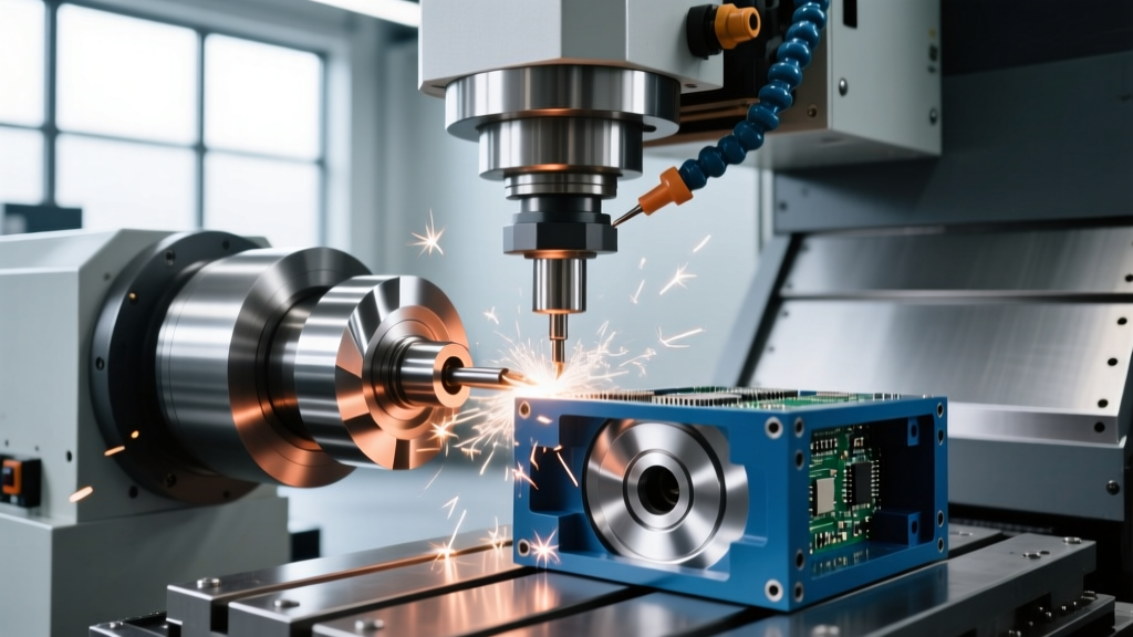
To achieve the continuous surface contact required for MIL-STD-461 EMI compliance, engineers increasingly rely on 5-axis CNC machining to produce complex, tight-tolerance enclosures in a single setup. This eliminates the cumulative stack-up errors inherent in multi-setup 3-axis operations.
⚠️ Critical Tolerance Thresholds for RF Shielding• Standard Consumer Electronics: ±0.003" to ±0.005" (Adequate for basic dust/moisture sealing)
• Automotive ECU Housings: ±0.002" (Required for environmental sealing and basic EMI)
• Aerospace/Defense RF Enclosures: ±0.0005" (Mandatory for continuous EMI gasket compression and waveguide alignment)
Why 5-Axis CNC Machining Outperforms 3-Axis for Complex Housings
Electronics enclosures rarely feature simple prismatic geometries. They require deep internal pockets for PCB standoffs, angled connector ports (like D-sub or circular mil-spec connectors), and thin-walled fins for passive cooling. While 3-axis machining requires flipping the part and re-indicating it—introducing microscopic alignment errors—5-axis CNC machining allows the cutting tool to approach the workpiece from virtually any angle in a single clamping.
| Feature Requirement | 3-Axis Approach (Multiple Setups) | 5-Axis Approach (Single Setup) |
|---|---|---|
| Angled Connector Ports | Requires custom angle plates; high risk of axis misalignment. | Machine head tilts to exact compound angle; perfect alignment to internal PCB. |
| Deep, Thin-Walled Pockets | Long tool extensions required; severe chatter and poor surface finish. | Shorter tools used by tilting the part; superior rigidity and finish. |
| Mating Flange Flatness | Flange machined in secondary setup; prone to parallelism errors. | Flange and internal pockets machined in same datum; ensures perfect parallelism. |
Case Study: Avionics Housing for LEO Satellites
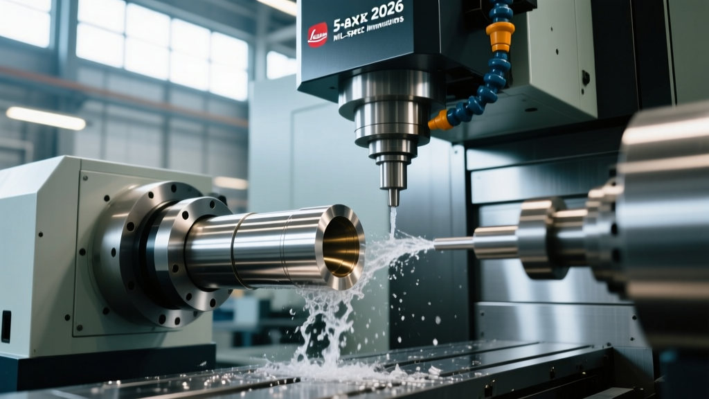
In a recent production run for a Low Earth Orbit (LEO) satellite communications payload, a manufacturer needed an avionics housing machined from Al 6061-T6. The design featured a central cavity with 0.040-inch (1.01 mm) thick walls to minimize weight, alongside angled waveguide interfaces. Using a 5-axis Hermle C42U machining center, the shop utilized trochoidal milling strategies with a 1/8-inch carbide endmill spinning at 24,000 RPM. By tilting the B and C axes, the machine maintained optimal tool engagement, eliminating the chatter that plagued initial 3-axis prototypes. The result was a housing that held a ±0.0005-inch flatness across the 12-inch mating flange, passing rigorous thermal vacuum (TVAC) and EMI testing on the first article.
Material Selection: Balancing Machinability, EMI, and Thermal Conductivity
The choice of alloy dictates both the machining strategy and the final performance of the enclosure. According to Sandvik Coromant's material engineering guidelines, aluminum alloys remain the dominant choice for electronics housings due to their favorable strength-to-weight ratio and thermal properties, but specific tempers and alloying elements drastically alter machinability.
- Aluminum 6061-T6: The industry workhorse. Offers excellent thermal conductivity (167 W/m·K) and good machinability. Best for general-purpose enclosures and passive heat sinks. Tooling note: Use uncoated or ZrN-coated carbide endmills to prevent aluminum adhesion (built-up edge).
- Aluminum 7075-T6: Significantly higher tensile strength (83 ksi vs 45 ksi for 6061) but lower thermal conductivity (130 W/m·K). Used in aerospace enclosures subject to high vibration or structural loads. Contains zinc and copper, which makes it slightly more abrasive to tooling.
- Magnesium AZ31B: Ultra-lightweight (35% lighter than aluminum) with exceptional vibration dampening and high EMI shielding effectiveness. Warning: Magnesium is highly flammable in chip form. Requires specialized machine shop fire suppression systems, strict chip evacuation protocols, and specific water-soluble coolants. Refer to NASA Workmanship Standards for stringent aerospace material handling protocols.
- Copper C101 (Oxygen-Free): Used exclusively for localized thermal spreaders or high-power RF enclosures. Extremely difficult to machine due to high ductility; requires razor-sharp, high-positive rake tooling and high-pressure coolant to manage stringy chips.
Cost Drivers and Pricing Framework for Production Runs
Understanding the cost structure of tight-tolerance 5-axis CNC machining is critical for hardware startups and procurement teams. Below is a realistic pricing framework for a 500-unit production run of a complex, 6x4x2 inch avionics enclosure in Al 6061-T6, reflecting 2026 machine shop rates.
| Cost Category | Estimated Cost (USD) | Notes & Variables |
|---|---|---|
| NRE (Programming & Fixture Design) | $2,500 - $4,000 | Includes 5-axis CAM toolpath generation and custom soft-jaw machining. |
| Raw Material (Per Part) | $45 - $60 | Based on aerospace-certified Al 6061-T6 billet with material traceability. |
| 5-Axis Machine Time | $140 - $180 / hour | Cycle time approx. 45 mins; includes tool wear and spindle depreciation. |
| Secondary Operations (Anodizing) | $15 - $25 / part | MIL-A-8625 Type II (for insulation) or Type III (for wear). Note: Masking EMI mating surfaces adds $8/part. |
| CMM Inspection (First Article) | $800 - $1,200 | Full AS9102 FAIR using a Zeiss CONTURA or equivalent coordinate measuring machine. |
If your enclosure requires EMI shielding, standard anodizing is an electrical insulator. You must either specify chemical conversion coating (MIL-DTL-5541 / Alodine), which is conductive but offers less corrosion resistance, or pay for precision masking during anodizing to leave mating surfaces bare. Failing to specify this in the RFQ will result in non-functional EMI gaskets.
Design for Manufacturability (DFM) Checklist for Enclosure Engineers
To minimize cycle times and prevent scrap during 5-axis CNC machining, CAD designers must adhere to strict DFM principles. Implementing these rules before submitting an RFQ will significantly reduce quoting friction and manufacturing costs.
- Internal Corner Radii: Never design sharp internal corners. The minimum internal radius should be at least 1.2x the diameter of the endmill required to reach the depth of the pocket. For a 0.500" deep pocket, use a 1/4" endmill, meaning the corner radius must be ≥ 0.125".
- Wall Thickness Limits: For aluminum enclosures, maintain a minimum wall thickness of 0.040" (1.0 mm) for small features and 0.080" (2.0 mm) for large, unsupported spans. Thinner walls will deflect under cutting forces, ruining tight tolerances.
- Thread Depth and Callouts: Limit blind tapped holes to a depth of 1.5x the thread diameter. For M3 threads, do not call out a tap depth greater than 4.5mm. Deeper taps increase the risk of tap breakage in blind pockets.
- Datum Alignment: Design the part so that all critical tolerance features ( mating flanges, precision dowel pin holes) can be accessed from the same Z-axis orientation. Forcing the machine to flip the part to finish a critical datum introduces unnecessary error.
Quality Assurance: Verifying Sub-Thou Tolerances
Machining a tight-tolerance enclosure is only half the battle; proving it to the client requires advanced metrology. For aerospace and medical electronics, visual inspection and calipers are unacceptable. Reputable machine shops utilize Coordinate Measuring Machines (CMM) and optical comparators.
For flatness and parallelism of EMI mating flanges, a CMM probe maps dozens of points across the surface to generate a true 3D topographical map of the variance. For complex internal geometries, such as angled waveguide channels, non-contact optical systems like the Keyence IM-8000 series can capture thousands of data points in seconds without risking probe deflection errors on thin walls. Always require a full dimensional report with your First Article Inspection (FAI) to ensure the shop's IPC and ISO 9001/AS9100 quality management systems are actively enforced on the shop floor.