OpenBuilds MiniMill CNC Machine: Operator Training and Setup Guide
Master the OpenBuilds MiniMill CNC machine with our operator training guide. Learn GRBL tuning, feeds/speeds, and workholding best practices.
Operational Profile and Hardware Limitations
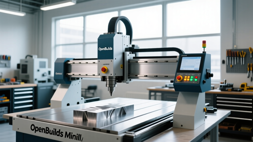
The OpenBuilds MiniMill CNC machine occupies a unique space in the desktop machining ecosystem. Bridging the gap between rigid 3D printers and entry-level industrial VMCs, this C-Beam aluminum extrusion-based router is engineered for light milling, PCB isolation, and precision plastics work. However, treating the MiniMill like a traditional cast-iron knee mill will result in broken tooling, lost steps, and poor surface finishes. Operator training must begin with a strict understanding of the machine's structural envelope.
Unlike belt-driven routers, the MiniMill utilizes ACME lead screws on NEMA 23 stepper motors, providing high holding torque but introducing backlash and binding risks if the gantry is not perfectly squared. The standard working envelope (approximately 240mm x 240mm x 100mm, depending on the specific Z-axis configuration) demands meticulous toolpath planning. Operators must account for the reduced Z-clearance when selecting tool stick-out and workholding heights.
⚠️ Critical Hardware Warning: Never run aggressive 3D adaptive clearing toolpaths in 6061 aluminum using the stock Makita RT0701C trim router spindle. The trim router lacks the low-end torque required for high chip-load evacuation, leading to tool deflection and spindle stall. For aluminum milling, upgrade to an 80mm 1.5kW or 2.2kW water-cooled VFD spindle to maintain consistent torque below 12,000 RPM.Pre-Flight Checklist and C-Beam Workholding
Proper workholding on the MiniMill is complicated by the C-Beam linear rail profile. Standard T-track clamps designed for 80/20 aluminum extrusions will not seat correctly. Operators must use hardware specifically matched to the OpenBuilds ecosystem.
M8 T-Slot Nut Integration and Tramming
- Verify T-Slot Hardware: The MiniMill's Y-axis and X-axis C-Beams require M8 T-slot nuts. Attempting to force M5 nuts into the C-Beam channel will strip the acrylic delrin nuts or jam the rail.
- Surface the Spoilboard: Before clamping any workpiece, face the MDF or phenolic spoilboard using a 1/2-inch 2-flute surfacing bit. Take a 0.5mm pass at 80 IPM to ensure the work plane is perfectly parallel to the spindle's XY travel.
- Tram the Z-Axis: Mount a dial indicator to the spindle collet. Sweep a 100mm radius circle on the spoilboard. Adjust the four M5 mounting bolts on the Z-axis plate until the indicator variance is within 0.02mm (0.001 inches) across the entire sweep.
- Apply Clamping Force: Use low-profile toe clamps to avoid Z-axis gantry collisions. For thin sheet materials (under 3mm), abandon mechanical clamps in favor of CNC-specific double-sided tape (e.g., Carbide 3D blue tape) paired with a cyanoacrylate (CA) glue wicking technique for absolute rigidity.
GRBL 1.1 Configuration for Micro-Stepping
The OpenBuilds BlackBox controller runs GRBL 1.1, a highly efficient open-source motion control firmware. Out-of-the-box settings are generalized for various OpenBuilds machines and must be dialed in specifically for the MiniMill's lead screw pitch and NEMA 23 micro-stepping configuration to prevent stalling during rapid directional changes.
According to the GRBL v1.1 Configuration Guide, junction deviation and acceleration parameters are the most common culprits for poor surface finishes on desktop machines.
| GRBL Parameter | Description | Recommended MiniMill Value |
|---|---|---|
$100, $101, $102 | Steps per millimeter (X, Y, Z) | 200.000 (for standard 8mm lead ACME screws) |
$110, $111, $112 | Max rate, mm/min (X, Y, Z) | 2500.000 (Do not exceed 3000 on ACME screws) |
$120, $121, $122 | Acceleration, mm/sec^2 | 150.000 (Lower than industrial VMCs to prevent frame flex) |
$11 | Junction deviation, mm | 0.020 (Increases smoothness on complex 2.5D contours) |
$120) is too high for the mass of the X-axis gantry. Drop the X-axis acceleration to 100 mm/sec^2 and re-test.Feeds, Speeds, and Tooling Matrix
Desktop CNC routers require a fundamentally different approach to chip load compared to heavy machinery. Because the MiniMill lacks the mass to dampen high-frequency vibrations, operators must prioritize tool geometry and chip evacuation over sheer material removal rates (MRR). As detailed in the CNC Cookbook Feeds and Speeds Masterclass, maintaining a proper chip load prevents work-hardening in metals and melting in thermoplastics.
Below is a baseline parameter matrix for the MiniMill equipped with an 80mm 1.5kW VFD spindle and standard ER11 collet holder. These values assume the use of premium carbide endmills (e.g., Harvey Tool or Destiny Tool) with appropriate coatings like ZrN for aluminum.
| Material | Tooling Specification | Spindle RPM | Feed Rate (IPM) | Depth of Cut (DOC) | Width of Cut (WOC) |
|---|---|---|---|---|---|
| 6061 Aluminum | 1/4' 3-Flute ZrN Carbide | 14,000 | 45 | 0.5mm (0.020') | 1.5mm (Slotting) |
| Delrin / Acetal | 1/4' 2-Flute O-Flute (Plastics) | 16,000 | 80 | 1.0mm (0.040') | 2.0mm |
| FR4 (PCB) | 0.8mm Carbide V-Bit (45°) | 12,000 | 30 | 0.15mm | Engraving |
| Corian / Solid Surface | 1/4' Single Flute Upcut | 18,000 | 100 | 2.0mm (0.080') | 3.0mm |
Troubleshooting Common Failure Modes
Operators must be trained to identify the auditory and visual cues of machine distress before catastrophic tool failure occurs. The lightweight nature of the OpenBuilds MiniMill build means that harmonic resonance occurs at different frequencies than heavy iron machines.
- Symptom: High-pitched squealing during aluminum slotting.
Diagnosis: Chip re-welding. The chips are not evacuating, melting against the flute, and causing friction.
Corrective Action: Increase feed rate by 15%, apply a mist of WD-40 or dedicated aluminum cutting fluid (e.g., Tap Magic), and switch to a 2-flute endmill to increase the flute valley volume for chip clearance. - Symptom: 'Stair-stepping' or layer shifts on the Y-axis.
Diagnosis: Lost steps due to Y-axis gantry binding or loose grub screws on the motor coupler.
Corrective Action: Power down the machine. Manually push the Y-axis gantry from end to end. If resistance spikes at any point, loosen the C-Beam mounting brackets, re-square the gantry using a precision machinist square, and re-tighten. Check the flexible motor coupler grub screws with a hex key. - Symptom: Z-axis plunges too deep during rapid direction changes.
Diagnosis: Z-axis lead screw backlash or ACME nut wear.
Corrective Action: Inspect the Delrin anti-backlash nut on the Z-axis. If the spring tension has degraded, replace the nut assembly. Ensure the Z-axis motor current (VREF) on the BlackBox controller is tuned to provide maximum holding torque without overheating the stepper.
Daily Maintenance Protocol
Extrusion-based CNC machines are highly susceptible to dust and chip ingress, which accelerates wear on the Delrin V-wheels and lead screws. Operators must execute the following protocol at the end of every shift:
- Evacuate the C-Beam Channels: Use a vacuum with a crevice tool to remove chips from the linear rail tracks. Embedded aluminum chips will flat-spot the Delrin V-wheels within 40 hours of operation.
- Lubricate the Lead Screws: Apply a dry PTFE (Teflon) lubricant to the X, Y, and Z ACME lead screws. Never use wet oils or lithium grease, as these will attract abrasive dust and form a grinding paste that destroys the nut threads.
- Inspect V-Wheel Preload: Spin the eccentric spacers on the X and Y carriage plates. The wheels should grip the C-Beam tightly enough to prevent lateral play, but loosely enough that the gantry can be pushed by hand without binding. Adjust the eccentric nuts using a 10mm wrench if play is detected.