Master CNC Milling Machining MW+ Maintenance Schedules
Optimize CNC milling machining MW+ maintenance schedules. Learn exact service intervals, spindle specs, and thermal controls for high-wattage 5-axis mills.
The High Stakes of MW+ Class CNC Maintenance
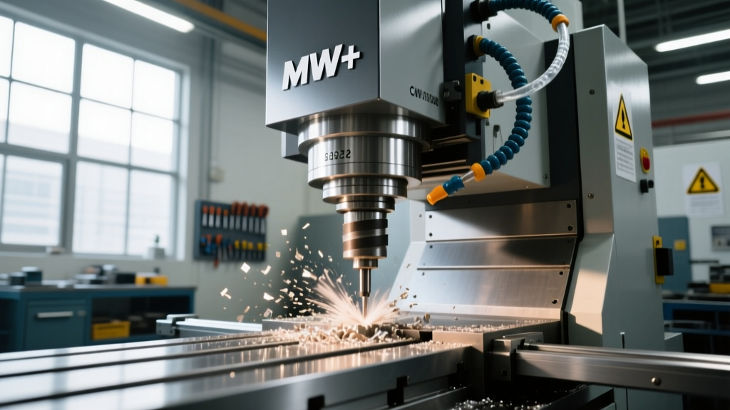
When managing a shop floor dedicated to cnc milling machining mw+ (Multi-Axis and High-Wattage) configurations, standard OEM maintenance manuals are merely the baseline. MW+ class machines—typically defined as 5-axis simultaneous machining centers equipped with 30kW to 50kW+ high-torque spindles and direct-drive torque tables—operate under extreme mechanical and thermal loads. These machines are the workhorses for aerospace titanium (Ti-6Al-4V) and Inconel 718 structural components, where cycle times can exceed 80 hours per part.
A catastrophic spindle failure or axis drift on a machine like a Hermle C52 or DMG MORI DMU 600 P doesn't just mean a $45,000 rebuild bill; it means scrapping a $120,000 near-net-shape titanium forging. To protect these assets, maintenance must shift from reactive to strictly predictive, governed by hard data and precise tolerances.
⚠️ Critical Downtime Warning: In MW+ aerospace milling, replacing a damaged HSK-A100 spindle taper due to micro-fretting corrosion costs between $12,000 and $18,000 in re-grinding and lost production. Automated taper cleaning cycles must be verified weekly.MW+ Spindle & Drive Train Service Matrix
High-wattage spindles generate immense internal heat and require specialized lubrication and cooling protocols. The following matrix outlines the non-negotiable service intervals for MW+ tier machining centers.
| Component | Interval | Action Required | Specification / Tolerance |
|---|---|---|---|
| Spindle Bearing Grease | Every 2,000 hrs | Purge and re-grease hybrid ceramic angular contact bearings | Kluber Isoflex NBU 15; exact volume per OEM (usually 3-5 cm³) |
| Spindle Chiller Fluid | Every 6 Months | Flush loop, replace glycol mixture, clean condenser fins | Maintain Delta-T within ±0.1°C of ambient room temperature |
| HSK Tool Retention Force | Weekly | Measure drawbar clamping force with a calibrated force gauge | HSK-A100: Minimum 18 kN (drop below 17 kN triggers immediate pull-stud replacement) |
| Torque Table Coolant | Every 12 Months | Replace direct-drive motor cooling fluid | Dielectric fluid; verify conductivity < 5 µS/cm |
| Axis Way Lube Filters | Every 3 Months | Replace positive pressure volumetric distributor filters | Filter mesh: 40 micron; verify system pressure at 15-20 bar |
Way Lube and Coolant Concentration in Heavy-Duty Milling
In MW+ setups, the cutting forces generated during heavy roughing of aerospace alloys place enormous shear stress on the linear guideways and ball screws. Standard way lubrication practices will lead to stick-slip phenomena and accelerated way cover degradation.
Way Lubrication Specifics
For machines with hardened box ways or heavy-duty roller linear guides, you must use an ISO VG 68 way lube with high tackiness additives to prevent wash-off from high-pressure flood coolant. Industry fluid management standards dictate that Mobil Vactra Oil No. 2 or an equivalent premium grade must be used. Verify the volumetric lube pump output at the furthest axis distribution block. If the pressure drop across the X-axis exceeds 15% compared to the pump head, the metering units are likely clogged with oxidized oil varnish.
Coolant Refractometry and Tramp Oil Control
Heavy milling of titanium requires high-lubricity semi-synthetic coolants (e.g., Trim MicroSol 585XT or Master Fluid Solutions TRIM E709) maintained at a strict 8% to 10% concentration. According to Sandvik Coromant's cutting fluid guidelines, failing to maintain this concentration in high-load milling leads to built-up edge (BUE) on carbide endmills and accelerated tool wear. Furthermore, MW+ machines utilize massive 500+ gallon sumps. You must install a continuous centrifugal tramp oil separator. If tramp oil exceeds 1.5% of the total volume, it will deplete the coolant's emulsifiers, leading to localized rust on the machine's cast iron base and workholding fixtures.
Axis Drive & Ball Screw Preload Verification
The Z-axis and Y-axis ball screws on MW+ machines endure severe axial loads. Over time, the preload applied during assembly degrades due to thermal cycling and mechanical shock from heavy interrupted cuts.
- Baseline Laser Interferometry: Every 6 months, run a Renishaw XL-80 laser interferometer test on all linear axes. Document the backlash and pitch error. If backlash on the X-axis exceeds 8 microns, the ball screw nut preload has degraded.
- Motor Current Signature Analysis (MCSA): Monitor the servo motor amperage during rapid traverses. A healthy X-axis rapid on a 10-ton table should draw a consistent baseline amperage. Spikes in current indicate binding ball screw support bearings or lack of lubrication.
- Support Bearing Preload Check: According to SKF's machine tool maintenance protocols, the fixed-end angular contact support bearings must maintain a preload equivalent to 8-12% of their dynamic load rating. If the bearing housing temperature exceeds 55°C during continuous 10m/min feed rates, the preload is excessively tight or the grease has broken down.
Managing Thermal Growth in High-Wattage Environments
The defining challenge of cnc milling machining mw+ environments is thermal equilibrium. A 40kW spindle operating at 12,000 RPM generates massive heat. If the spindle chiller is set to a static 20°C, but the ambient shop temperature fluctuates from 18°C at night to 24°C in the afternoon, the spindle will physically expand or contract relative to the machine bed.
To solve this, modern MW+ machines utilize ambient-tracking chillers. The chiller's setpoint must dynamically track the ambient room temperature sensor located near the machine base, maintaining a strict ΔT (Delta T) of ±0.1°C. Additionally, ensure the machine's internal thermal compensation sensors (usually embedded in the Z-axis casting and spindle housing) are free of coolant splash and calibrated annually. If the Z-axis thermal compensation model in the CNC control (e.g., Siemens Sinumerik ONE or Fanuc 31i-B5) is disabled to 'save time' during setup, expect Z-depth errors of up to 60 microns over an 8-hour shift.
Frequently Asked Questions
How often should I replace the hydraulic fluid in an MW+ tool magazine?
High-capacity chain or matrix tool magazines (120+ tools) rely on hydraulic power packs for rapid tool exchanges. Replace the hydraulic fluid (typically ISO VG 32 or 46 anti-wear) every 4,000 operating hours. More importantly, replace the 10-micron return line filters every 1,000 hours to prevent servo-valve spool stiction, which causes the tool changer arm to hesitate and crash into the spindle taper.
What is the acceptable runout for an HSK-A100 spindle under load?
Static runout measured at the spindle nose with a precision test arbor should be less than 3 microns (0.00012 inches). However, under dynamic load, thermal expansion and bearing deflection can increase this. If dynamic runout measured via a non-contact laser sensor exceeds 8 microns during heavy side-milling, the spindle bearings require immediate pre-load adjustment or replacement.
Can I use standard compressed air for spindle taper cleaning?
No. Standard shop air contains moisture and particulate matter that will pit the HSK taper. MW+ machines must use an integrated spindle air-blast system fed by a dedicated, refrigerated air dryer delivering ISO 8573-1 Class 1.2.1 air quality (max particle size 0.1 µm, dew point -40°C). Moisture in the taper leads to micro-corrosion, which ruins tool retention and causes high-speed vibration.