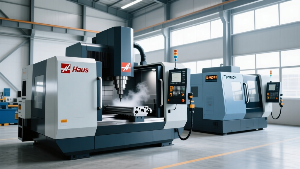
Optimizing Spindle Speed and Feed Rates on a Vertical CNC Machine
Master spindle speed and feed rate optimization for your vertical CNC machine. Learn exact formulas, material parameters, and chatter prevention.
The Physics of Chip Formation on a Vertical CNC Machine
Optimizing cutting parameters on a vertical CNC machine (VMC) requires balancing the kinematics of the spindle with the mechanical limits of the Z-axis column and the metallurgical properties of the workpiece. Unlike horizontal machining centers (HMCs), VMCs must contend with gravity-driven chip recutting in deep pockets and specific Z-axis thrust bearing loads during heavy axial engagements. Calculating the correct spindle speed (RPM) and feed rate (IPM) is not merely about avoiding tool breakage; it is about controlling the heat partition in the shear zone and maintaining dimensional accuracy across the machine's travel envelope.
Modern VMCs, such as the Haas VF-2SS or DMG MORI CMX 600V, feature high-speed inline direct-drive spindles capable of 12,000 to 14,000 RPM. However, running a cutter at maximum RPM without matching the feed rate to the chip load will result in catastrophic edge wear. The goal is to generate a chip thick enough to carry heat away from the cutting edge, but thin enough to avoid exceeding the shear strength of the workpiece material.
Core Kinematic Formulas (Imperial & Metric)
Spindle Speed (RPM):
Imperial: RPM = (SFM × 3.82) / Cutter Diameter (inches)
Metric: n = (Vc × 1000) / (π × Cutter Diameter (mm))
Feed Rate (IPM / mm/min):IPM = RPM × Feed Per Tooth (FPT) × Number of Flutes (Z)
SFM = Surface Feet per Minute | Vc = Cutting Speed (m/min)
Baseline Parameters: Material vs. Cutter Matrix
The following matrix provides baseline parameters for a standard 1/2-inch (12.7mm) 4-flute AlTiN-coated solid carbide end mill. These values assume a rigid VMC setup with a tool stick-out (L/D ratio) of less than 3:1 and a radial depth of cut (RDOC) of 50% of the cutter diameter.
| Workpiece Material | SFM (Surface Feet/min) | Calculated RPM | FPT (Inches) | IPM (Inches/min) |
|---|---|---|---|---|
| 6061-T6 Aluminum | 1,000 | 7,640 | 0.0040 | 122.2 |
| 304 Stainless Steel | 250 | 1,910 | 0.0020 | 15.3 |
| Ti-6Al-4V (Titanium) | 150 | 1,146 | 0.0015 | 6.9 |
For authoritative baseline data on specific cutter geometries and proprietary coatings, refer to the Harvey Tool Technical Guides or the Sandvik Coromant Milling Knowledge base. These resources account for variables like helix angle and flute pitch that alter baseline speeds.
The Radial Chip Thinning Trap
A common programming error on VMCs occurs when machining thin walls or performing finishing passes with a low radial depth of cut (RDOC). When the RDOC is less than 50% of the cutter diameter, the cutting edge enters and exits the material at an angle, producing a chip that is physically thinner than the programmed Feed Per Tooth (FPT).
If you do not compensate for radial chip thinning by increasing the feed rate, the cutter will rub against the workpiece instead of shearing it. This generates massive amounts of friction heat, rapidly destroying the AlTiN coating and causing premature flank wear.
Calculating the Adjusted Feed Rate
To maintain the nominal chip thickness and leverage the heat-resistant properties of modern carbide substrates, you must apply a chip thinning multiplier. For example, if you are profiling a titanium aerospace bracket with a 1/2-inch end mill at a 10% RDOC (0.050 inches):
- Identify the RDOC ratio: 0.050 / 0.500 = 0.10 (10%).
- Apply the multiplier: At 10% RDOC, the chip thinning factor is approximately 1.35.
- Adjust the FPT: Multiply your baseline FPT (0.0015 for Titanium) by 1.35 to get an adjusted FPT of 0.0020.
- Recalculate IPM: 1,146 RPM × 0.0020 × 4 flutes = 9.1 IPM (up from the baseline 6.9 IPM).
This adjustment ensures the cutting edge penetrates the work-hardened layer of the material, extending tool life by up to 40% in high-speed finishing operations.
VMC-Specific Mechanical Constraints
Optimizing feeds and speeds on a vertical machining center requires accounting for the machine's specific structural dynamics. The vertical orientation introduces unique mechanical constraints that dictate how aggressive your parameters can be.
Z-Axis Thrust & Pitch Error
During heavy slotting or drilling, axial cutting forces push directly up the Z-axis. If the VMC uses linear guides rather than box ways, excessive axial load can cause microscopic Z-axis pitch error. To mitigate this, limit the axial depth of cut (ADOC) to 1.5x the cutter diameter and use trochoidal toolpaths to distribute the load radially rather than axially.
Gravity & Chip Evacuation
In a VMC, chips fall directly back into the cut zone. Recutting chips in deep pockets causes edge chipping. When machining deep cavities, you must reduce the programmed feed rate by 10-15% unless the VMC is equipped with Through-Spindle Coolant (TSC) at a minimum of 1,000 PSI to forcefully evacuate chips from the shear zone.
Troubleshooting Decision Tree: Chatter and Edge Chipping
When theoretical speeds and feeds fail in practice, the issue is usually harmonic resonance or tool deflection. Use this diagnostic framework to adjust your VMC parameters on the fly.
- Symptom: High-pitched squealing or visible chatter marks on the finished surface.
Root Cause: The spindle RPM is exciting the natural harmonic frequency of the tool-holder-workpiece system.
Correction: Do not change the feed rate. Reduce the spindle RPM by 10-15% to shift out of the harmonic node, or increase the RDOC to increase damping forces. If using a standard ER32 collet, upgrade to a hydraulic or shrink-fit holder to increase radial stiffness. - Symptom: Built-Up Edge (BUE) on the cutting flutes when machining 6061-T6 Aluminum.
Root Cause: The feed rate is too slow, or the cutter lacks a polished flute geometry, causing aluminum to weld to the carbide.
Correction: Increase the FPT by 20% to generate a thicker chip that strips material away from the rake face. Switch to an uncoated, high-polish carbide end mill designed specifically for non-ferrous materials, and apply flood coolant or Minimum Quantity Lubrication (MQL). - Symptom: Tapered walls or out-of-tolerance pocket dimensions.
Root Cause: Radial tool deflection due to excessive stick-out (L/D ratio > 4:1) combined with high radial cutting forces.
Correction: Implement an adaptive clearing (trochoidal) toolpath. Maintain a constant, low RDOC (5-8% of cutter diameter) while maximizing the ADOC and feed rate. This keeps lateral forces on the VMC's Y-axis linear guides within acceptable limits.
Advanced Spindle Thermal Considerations
When running high-speed machining (HSM) cycles on a VMC for extended periods, spindle thermal growth becomes a critical variable. A standard cast-iron VMC column can experience Z-axis thermal displacement of 0.0005 to 0.0015 inches per hour as the spindle bearings generate heat. If your optimized parameters rely on tight axial tolerances (e.g., facing operations to ±0.0002 inches), you must integrate macro variables or probe cycles to map and compensate for Z-axis thermal drift dynamically throughout the shift.