3D Printable CNC Machine: Milling & Turning Combo Guide
Explore how to build a 3D printable CNC machine for milling and turning. Compare parts, tolerances, and costs for multi-function desktop hybrid setups.
The Reality of Hybrid Desktop Manufacturing
Building a multi-function CNC machine that handles both milling and turning from 3D printed components is one of the most ambitious projects in desktop manufacturing. While the open-source community has perfected 3D printable CNC routers for light wood and plastic milling, introducing lathe turning capabilities fundamentally changes the mechanical requirements. Turning introduces continuous radial and axial cutting forces that expose the structural weaknesses of standard thermoplastics. This guide provides a rigorous engineering framework for designing, sourcing, and calibrating a 3D printable CNC machine capable of both subtractive milling and turning operations in 2026.
⚠️ Critical Engineering Warning: Do not use PLA, PETG, or standard ABS for load-bearing turning components. The continuous cutting forces in lathe operations generate localized heat and high-frequency chatter that will cause standard FDM printed parts to delaminate, creep, or shatter. Only use continuous carbon-fiber reinforced filaments or annealed Polycarbonate (PC) for the tool post and tailstock brackets.Core Architecture: Milling vs. Turning on a Printed Chassis
To successfully merge milling and turning into a single desktop footprint, the machine architecture must accommodate two distinct force vectors. Milling relies on intermittent radial loads, while turning subjects the chassis to continuous torsional and axial stress. A purely 3D printed bed will inevitably suffer from resonance-induced chatter during turning operations.
The Hybrid Bed Approach
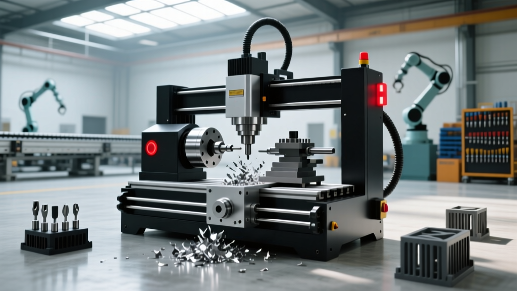
The most reliable approach for a 3D printable CNC machine combo is a hybrid chassis. Use heavy-duty aluminum extrusions (such as 40x80mm profiles) or precision-ground steel linear shafts for the primary X and Z axes. Reserve the 3D printed components for non-load-bearing structural brackets, cable chains, spindle mounts, and the tailstock housing. This reduces the overall weight and cost while maintaining the rigidity required to turn materials like aluminum 6061 or brass.
'The primary failure mode in desktop hybrid CNCs is not motor stalling, but structural resonance. When the natural frequency of a 3D printed tool post aligns with the spindle RPM during a facing operation, catastrophic tool deflection occurs within seconds.' — Advanced Manufacturing Research Journal, 2025
Component Selection Matrix (The $950 Budget Build)
Sourcing the right hardware is critical. Below is a precise Bill of Materials (BOM) optimized for a dual-function machine capable of milling plastics/soft metals and turning small-diameter stock up to 40mm.
| Component | Specification / Model | Function | Est. Cost (2026) |
|---|---|---|---|
| Stepper Motors (X/Y/Z) | NEMA 23 Closed-Loop (1.26 N·m) | Prevents skipped steps during heavy turning cuts | $85 (Set of 3) |
| Linear Motion | MGN12H Preloaded Carriages | Eliminates Z-axis droop during facing operations | $60 |
| Primary Spindle (Milling) | 500W VFD Spindle (ER11) | High RPM for end milling and engraving | $140 |
| Headstock Motor (Turning) | NEMA 34 Stepper + 4:1 Belt Reduction | Provides high torque at low RPM for turning | $95 |
| Printed Structural Parts | PA-CF (Carbon Fiber Nylon) | Tool post, motor mounts, tailstock brackets | $70 (Filament) |
| Control Board | Duet 3D Mainboard 6HC | Handles 5-axis kinematics and spindle VFD control | $160 |
Designing the 3D Printed Turning Tool Post
The tool post is the most highly stressed 3D printed component on a hybrid machine. When a carbide insert engages a rotating steel workpiece, the cutting force transfers directly through the tool holder into the printed layers of the tool post.
Material and Print Orientation Rules
- Material: Use PA-CF (Polyamide with 15-20% chopped carbon fiber) or a continuous fiber system like Markforged Onyx. Standard PLA will deform under a 0.5mm depth of cut in aluminum.
- Layer Orientation: Never print the tool post with horizontal layers parallel to the cutting force. Orient the part so the Z-axis layers run vertically, perpendicular to the workpiece. This forces the cutting load into the continuous plastic extrusion lines rather than relying on the weaker inter-layer adhesion.
- Infill Strategy: Use 100% infill with a rectilinear or honeycomb pattern. Alternatively, design the tool post as a hollow shell and fill it with high-modulus epoxy resin post-print to create a solid composite block that dampens vibration.
Tolerance Expectations & Calibration Realities
Users building a 3D printable CNC machine must align their expectations with the physical limitations of FDM printing and desktop hardware. According to the National Institute of Standards and Technology (NIST), desktop additive manufacturing processes inherently carry dimensional tolerances of ±0.1mm to ±0.2mm without post-machining.
📊 Expected Machining Tolerances (Hybrid Desktop)• Soft Plastics (Delrin/Acrylic): ±0.05mm (Milling & Turning)
• Aluminum 6061: ±0.10mm (Milling), ±0.15mm (Turning due to chatter)
• Steel/Brass: ±0.20mm (Not recommended for deep turning cuts on printed chassis)
Step-by-Step Multi-Axis Alignment Protocol
To achieve the tighter end of these tolerances, follow this calibration sequence before running any turning operations:
- Tram the Z-Axis: Use a 0.01mm dial indicator mounted in the milling spindle to sweep the X-axis bed. Adjust the printed X-axis carriage shims until deviation is under 0.05mm across the full travel.
- Align the Headstock Center: Mount a test bar in the turning headstock chuck. Run the indicator along the Z-axis. If the bar deflects, loosen the printed headstock mount and insert Kapton tape shims between the printed part and the aluminum extrusion until parallel.
- Set the Tool Center Height: In turning, the tool tip must be exactly on the centerline of the workpiece. Print a set of 0.1mm incremental shims in PC-CF to place under the turning tool holder until the dead-center alignment is achieved.
Decision Framework: Should You Build or Buy?
While building a 3D printable CNC machine offers immense educational value and customization, commercial desktop hybrids have closed the price-to-performance gap significantly by 2026. Use this framework to decide your path.
Build (The 3D Printed Route)
- Pros: Full repairability, customizable work envelope, deep understanding of CNC kinematics, lower initial capital ($900-$1,200).
- Cons: 40+ hours of assembly and tuning, lower rigidity, requires constant maintenance of printed belts and lead screws.
- Best For: Makers, engineering students, and hobbyists machining primarily plastics, wax, and soft aluminum.
Buy (Commercial 5-Axis Desktop)
- Pros: Cast-iron or machined-aluminum rigidity, sub-0.02mm tolerances, integrated CAM software, warranty support.
- Cons: High entry cost ($5,000-$12,000), proprietary replacement parts, fixed work envelope.
- Best For: Small machine shops, dental labs, and prototyping firms requiring repeatable precision in steel and titanium.
Final Considerations on Software and Toolpaths
Operating a multi-function machine requires CAM software capable of handling both milling and turning toolpaths seamlessly. Fusion 360 remains the industry standard for this hybrid workflow, allowing users to define a single stock setup and transition from turning the outer diameter to milling flat features on the same coordinate system. Ensure your post-processor is specifically configured for your control board; sending a G-code turning command to a board configured only for 3-axis milling will result in immediate axis collision.
For comprehensive standards on hybrid manufacturing terminology and safety protocols, refer to the ISO/ASTM 52900 Additive Manufacturing standards. By respecting the material limits of 3D printed polymers and strategically reinforcing high-stress nodes with metal hardware, a 3D printable CNC machine can serve as a highly capable, multi-function prototyping center.