Training on 3-Axis CNC Machine Models: Setup and Capability Guide
Master 3-axis CNC machine models with our expert setup guide. Compare Haas, DMG MORI, and Tormach capabilities, workholding, and pre-flight checklists.
Executive Summary: Operator Training Directives
Transitioning from manual machining or basic CAM programming to operating professional 3-axis CNC machine models requires a rigorous understanding of machine kinematics, workholding physics, and setup metrology. This training guide dissects the operational capabilities of three industry-standard platforms—the Haas VF-2SS, DMG MORI CMX 600V, and Tormach 1100MX. By standardizing your pre-flight setup protocol, verifying tool length offsets (TLS) with sub-micron accuracy, and applying material-specific parameter baselines, operators can eliminate 90% of setup-induced spindle crashes and achieve first-part accuracy on complex 3D contouring operations.
Capability Matrix: Leading 3-Axis CNC Machine Models
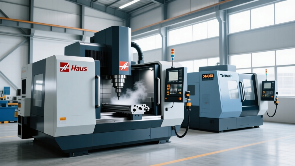
Before initiating any setup, operators must understand the physical limits and thermal characteristics of their specific equipment. The following matrix compares three dominant 3-axis CNC machine models across critical production metrics for 2026 job shop environments.
| Machine Model | Travel (X, Y, Z) | Spindle Speed & Taper | ATC Capacity | Rapid Traverse | Approx. Base Price (2026) |
|---|---|---|---|---|---|
| Haas VF-2SS | 30' x 20' x 20' | 12,000 RPM (CT40) | 24+1 Side-mount | 1,400 IPM | $72,000 - $78,000 |
| DMG MORI CMX 600V | 23.6' x 22' x 20.1' | 12,000 RPM (BT40) | 20 Arm-type | 945 IPM | $115,000 - $130,000 |
| Tormach 1100MX | 28' x 16.5' x 16' | 10,000 RPM (BT30) | 10 Arm-type | 500 IPM | $14,500 - $16,000 |
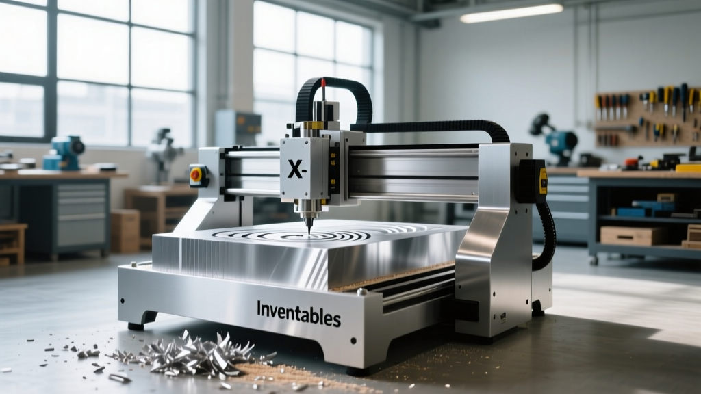
The Haas VF-2SS remains the benchmark for high-speed aluminum milling, leveraging its 1,400 IPM rapids to minimize non-cutting time. Conversely, the DMG MORI CMX 600V utilizes a heavier cast-iron column and linear guideways optimized for dampening high-frequency vibrations during aggressive stainless steel or titanium roughing. The Tormach 1100MX, while limited by its BT30 taper and lower mass, offers unparalleled accessibility for prototyping and secondary operations where rapid ATC (Automatic Tool Changer) cycling is prioritized over heavy material removal rates (MRR).
The 5-Step Pre-Flight Setup Protocol
Variance in machine setup is the primary catalyst for scrapped parts and catastrophic crashes. Operators must execute the following deterministic sequence before loading G-code into the control.
1. Thermal Stabilization and Spindle Warm-Up
Cast iron and steel machine components expand as friction generates heat in the spindle bearings and axis motors. On a standard Haas VF-2SS, thermal growth can shift the Z-axis coordinate by up to 0.0015 inches in the first 45 minutes of operation. Always run a 15-minute spindle warm-up macro (typically cycling from 1,000 RPM to 8,000 RPM in 1,000 RPM increments) while simultaneously jogging the X and Y axes to full travel limits. This distributes way oil and stabilizes the ballscrew temperature.
2. Workholding Metrology and Vise Tramming
A 6-inch Kurt-style CNC vise must be trammed to the machine table within 0.0005 inches over a 12-inch sweep. Mount a 0.0005-inch resolution dial test indicator on the spindle. Sweep the fixed jaw of the vise. If the indicator reads more than 0.0005 inches of deviation, loosen the center hold-down bolt and tap the vise with a soft-face mallet until it reads zero. Once trammed, torque the center bolt to 90 ft-lbs and re-check the indicator, as over-torquing can distort the vise base and pull it out of alignment.
3. Parallel Seating and Clamping Force
When loading raw stock onto parallels, operators must ensure the material is fully seated. Use a dead-blow hammer to strike the top of the stock while applying clamping pressure. Verify seating by attempting to slide a 0.001-inch feeler gauge between the stock and the parallels. If the gauge slides through, the part is not seated, which will result in Z-axis depth errors and potential part ejection during heavy roughing passes.
4. Tool Length Offset (TLS) Calibration
Never rely on manual paper-touch methods for TLS on production 3-axis CNC machine models. Utilize a spindle-mounted electronic tool setter (such as a Renishaw NC4 or Haas WIPS) or a Haimer 3D Sensor. For manual TLS, use a 1-2-3 block and a feeler gauge, but always account for the exact gauge thickness in the control's geometry offset page. Ensure the tool tip is clean and free of chips before triggering the setter; a single 0.002-inch aluminum chip stuck to the tool tip will result in a guaranteed Z-axis crash.
5. Work Coordinate System (WCS) Verification
Establish your G54 (or G55-G59) WCS using an electronic edge finder. After picking the X and Y datums, perform a dry run with the Z-axis offset shifted up by +5.000 inches. Run the first 50 lines of the G-code in single-block mode with rapid overrides set to 25%. Visually verify that the tool path aligns with the physical stock boundaries before removing the Z-axis shift.
⚠️ Critical Failure Mode: Z-Axis Crash Vectors
The most common cause of spindle crashes on 3-axis CNC machine models is failing to clear the Z-axis wear offset after a tool change. If an operator measures a new tool but forgets to input the new geometry offset, the machine will attempt to cut at the previous tool's Z-depth. Rule of Thumb: Always verify the 'Tool Number' matches the 'Offset Number' on the control screen before pressing Cycle Start. Adhering to strict OSHA machine guarding and operational safety standards requires operators to maintain physical readiness at the E-Stop button during the initial plunge move of any new tool.
Material-Specific Parameter Baselines
Optimizing feeds and speeds requires balancing Material Removal Rate (MRR) with tool deflection and thermal management. The following parameters assume the use of premium 3-flute and 4-flute solid carbide endmills with appropriate AlTiN or ZrN coatings.
| Material | Tooling Spec | Spindle RPM | Feed Rate (IPM) | Radial DOC (WOC) | Axial DOC | Coolant Strategy |
|---|---|---|---|---|---|---|
| 6061-T6 Aluminum | 3-Flute Carbide, 0.500' Dia, ZrN | 10,000 | 90 | 0.250' (50%) | 0.750' (1.5xD) | Flood + Air Blast |
| 304 Stainless Steel | 4-Flute Carbide, 0.375' Dia, AlTiN | 2,200 | 11 | 0.020' (5%) | 0.375' (1xD) | High-Pressure TSC |
| 1018 Cold Rolled Steel | 3-Flute Carbide, 0.500' Dia, TiCN | 4,500 | 36 | 0.125' (25%) | 0.500' (1xD) | Flood Coolant |
When machining 6061-T6 aluminum, chip evacuation is the primary limiting factor. Utilizing a 50% Width of Cut (WOC) allows the flutes sufficient space to clear chips. If chips are re-cut, they will weld to the cutting edge, leading to premature tool failure. For 304 Stainless Steel, work hardening is a severe risk. Never allow the tool to dwell; maintain a constant feed rate and utilize a 5% WOC adaptive clearing toolpath to keep cutting forces low and heat out of the workpiece.
Advanced Operator Best Practices: Smart Probing and IoT
Modern 3-axis CNC machine models are increasingly integrated with smart probing systems and IoT monitoring platforms. According to research highlighted by NIST Smart Connected Manufacturing initiatives, shops that implement automated part probing reduce setup times by an average of 40% while eliminating manual measurement errors.
Operators should utilize spindle-mounted probes (like the Renishaw OMP60) to automatically update WCS datums and perform in-cycle part verification. For example, after roughing a pocket, program a probing routine to measure the pocket floor. If the probe detects 0.002 inches of excess material due to tool deflection, the control can automatically update the Z-axis wear offset before executing the semi-finish pass. This closed-loop feedback is essential for holding tight geometric dimensioning and tolerancing (GD&T) profiles on aerospace and medical components.
Furthermore, leveraging SME Machining Technologies guidelines for machine monitoring allows operators to track spindle load meters in real-time. A sudden spike in spindle load during a constant-engagement toolpath indicates a dull tool or a chip jam. By setting macro variables to trigger a feed-hold when the spindle load exceeds 85% of its rated continuous capacity, operators can prevent catastrophic tool breakage and save thousands of dollars in scrapped raw material and replacement tooling costs.
Final Inspection and Documentation
Upon completing the first article, do not immediately run the batch. Remove the part, deburr the edges, and perform a full CMM (Coordinate Measuring Machine) or manual micrometer inspection. Document the actual tool wear offsets required to hit nominal dimensions in your shop's CAM setup sheet. This historical data transforms a one-off setup into a repeatable, highly optimized production process, ensuring that the next operator running these 3-axis CNC machine models achieves first-part accuracy from the moment the cycle starts.