Hand Wheel CNC Machine Setup: 3-Axis Operator Best Practices
Master 3-axis VMC setup with our hand wheel CNC machine operator guide. Learn MPG step multipliers, work offset probing, and crash prevention tactics.
The Role of the MPG in 3-Axis VMC Operations
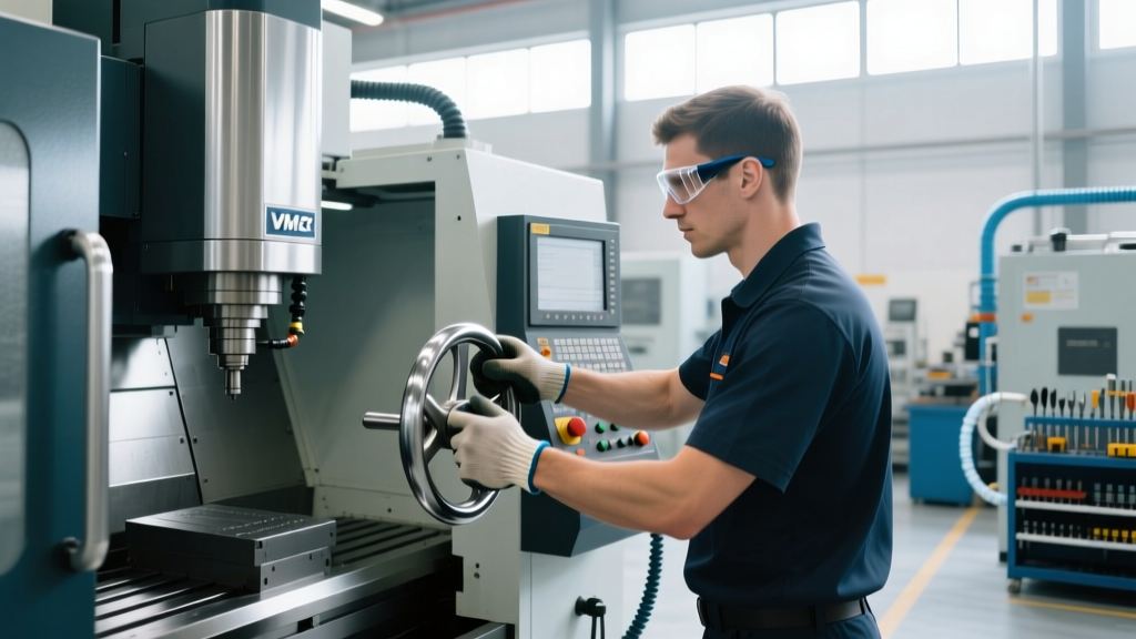
The Manual Pulse Generator (MPG), universally known on the shop floor as the hand wheel, remains the most critical tactile interface between a CNC operator and a 3-axis Vertical Machining Center (VMC). While modern 3-axis CNC machines feature advanced automatic probing cycles and CAD/CAM integration, the physical hand wheel is irreplaceable for initial work offset setup, tool length verification, and manual crash-avoidance jogging. For machines like the Haas VF-Series Vertical Mills, mastering the electronic handwheel is the dividing line between a novice who crashes spindles and a senior machinist who holds tenths-level tolerances.
This guide details the exact protocols, step-multiplier management, and edge-case troubleshooting required for safe and precise 3-axis CNC machine setup using the hand wheel.
Anatomy of the 3-Axis Hand Wheel Interface
A standard 3-axis CNC pendant houses an optical encoder handwheel that typically generates 100 pulses per full 360-degree revolution. The control software translates these pulses into axis movement based on the selected step multiplier. Understanding the exact mathematical translation of these clicks is mandatory for operator certification.
- x1 Multiplier: 1 click = 0.0001 inch (or 0.001 mm). Used for final Z-axis touching and precision edge-finding.
- x10 Multiplier: 1 click = 0.001 inch. Used for approaching the workpiece and setting X/Y work offsets.
- x100 Multiplier: 1 click = 0.010 inch. Used strictly for rapid traversing across the table or moving up the Z-axis column. Never use this for approach vectors.
The most common catastrophic failure in 3-axis CNC training occurs when an operator leaves the MPG on the x100 multiplier while jogging the Z-axis downward. At x100, a single accidental click moves the spindle 0.010 inches. If the operator is performing a Z-zero touch-off with a tool setter or gauge block, a single inadvertent bump of the handwheel can drive the cutting tool directly through the workpiece, shattering the carbide endmill and damaging the machine table. Best Practice: Always physically verify the multiplier switch position with your eyes before rotating the wheel toward the workpiece.
Step-by-Step 3-Axis Work Offset Setup (G54)
Setting the G54 work coordinate system using a standard 0.200-inch diameter edge finder requires a specific, repeatable sequence. As detailed in standard CNC Machine Coordinates and Work Offsets training, consistency in approach direction eliminates backlash errors.
1. X and Y Axis Edge Finding
- Mount the 0.200-inch edge finder in the spindle and indicate the Z-height to approximately 0.100 inches above the workpiece surface.
- Set the hand wheel to the x100 multiplier to rapidly position the edge finder near the X-axis edge of the stock.
- Switch to the x10 multiplier. Jog the Y-axis (perpendicular to the edge) until the edge finder tip deflects (kicks out).
- Switch to the x1 multiplier. Back off the edge by 0.050 inches, then slowly approach the edge again until the tip kicks out. This eliminates screw backlash.
- With the tip deflected, go to the control's OFFSET page, select G54, highlight X, and type the machine's mechanical X-coordinate minus 0.100 inches (the radius of the edge finder). Alternatively, use the control's 'Measure Part' macro if available.
- Repeat the exact backlash-elimination process for the Y-axis.
2. Z-Axis Tool Length Offset (TLO) and Z-Zero
The Z-axis requires the highest hand wheel sensitivity. Never use the x10 or x100 multipliers within 1.000 inch of the workpiece surface during Z-setup.
- Switch to a dedicated Z-axis setting tool (such as a Haimer 3D Sensor or a 2.000-inch precision gauge block).
- Using the x1 multiplier, lower the spindle in 0.0001-inch increments.
- Stop immediately when the gauge block slides under the tool with slight drag, or when the dial indicator on the 3D Sensor hits zero.
- Input the Z mechanical coordinate directly into the Tool Length Offset registry for that specific tool number.
Capabilities Matrix: Hand Wheel vs. MDI vs. Auto Probing
Operators must know when to rely on the hand wheel CNC machine interface versus typing G-code in the Manual Data Input (MDI) line or triggering automatic macro cycles. The following matrix outlines the optimal method for common 3-axis setup tasks.
| Setup Task | Optimal Method | Why This Method? |
|---|---|---|
| Initial Stock Location (G54 X/Y) | Hand Wheel (x10 / x1) | Provides tactile feedback and visual confirmation of edge finder deflection. |
| Bore Center Finding | MDI (G65 P9832) | Automatic probing routines calculate true center mathematically, eliminating human error. |
| Z-Axis Touch Off (Gauge Block) | Hand Wheel (x1) | Allows the operator to feel the exact drag of the gauge block, preventing over-travel. |
| Verifying Safe Clearance Planes | Hand Wheel (x100) | Rapidly moves the spindle to the G53 Z-home position without waiting for programmed G0 feedrates. |
Real-World Edge Case: Thermal Expansion and Z-Axis Drift
A frequent failure point in 3-axis CNC machining is ignoring thermal growth during long production runs. A standard cast-iron VMC column will expand as the spindle bearings and axis motors generate heat. On a machine like the Haas VF-2, the Z-axis can easily grow by 0.0005 to 0.0015 inches over the first four hours of operation.
The Operator Protocol: If you set your Z-axis work offsets cold at 6:00 AM, your Z-depths will be cutting too deep by 10:00 AM. Senior operators use the hand wheel to perform a 'warm-up verification'. After the machine's programmed warm-up cycle (typically 15 minutes of spindle and axis movement), the operator manually jogs the spindle down to the Z-setting tool using the x1 hand wheel multiplier. If the gauge block no longer fits, or fits too loosely, the operator must adjust the G54 Z-offset or the Tool Wear offset to compensate for the thermal drift. Relying solely on the initial cold setup without hand wheel verification guarantees scrapped parts in high-tolerance aerospace or medical milling.
Preventative Maintenance for the MPG Pendant
The hand wheel CNC machine pendant is subjected to harsh environments, including way oil mist, aluminum chips, and constant physical manipulation. To maintain the 100-pulse-per-revolution accuracy, operators must adhere to the following maintenance schedule:
- Cable Wrap Management: The coiled cable connecting the pendant to the machine cabinet is prone to internal wire fatigue. Never let the pendant hang by the cable. Always use the magnetic back or hook it onto the enclosure door to prevent internal copper strand breakage, which causes 'ghost clicks' or axis stuttering.
- Optical Encoder Cleaning: If the hand wheel feels physically smooth but the axis movement on the screen stutters or jumps, the internal optical encoder disk is likely contaminated with oil mist. Use compressed air (under 30 PSI) to blow out the encoder housing seams. Do not spray WD-40 or solvent into the dial, as this will destroy the optical sensors.
- Switch Contact Verification: The axis selector and multiplier switches are mechanical toggles. If the X-axis selector requires wiggling to register on the screen, the internal contacts are oxidized. Cycle the switch rapidly 20 times to clean the contacts via friction before requesting an electrical replacement.
Frequently Asked Questions (FAQ)
Why does my hand wheel move the axis in the wrong direction?
Most CNC controls feature a 'Jog Invert' parameter. If the hand wheel clockwise rotation moves the axis in the negative direction, check the machine parameters (e.g., Haas Parameter 318 or Fanuc Parameter 3108). Operators should never physically rewire the encoder to fix this; always use the control's software inversion to maintain standardized G-code logic.
Can I use the hand wheel to manually mill a contour?
While you can manually jog X and Y simultaneously using the hand wheel, the resulting surface finish will be heavily scalloped due to the inconsistent pulse rate of human hand rotation. For manual contouring, use the MDI line to program a G1 linear interpolation move at a programmed feedrate (e.g., G1 X2.0 Y3.0 F15.0), which allows the control's servo drives to execute a perfectly smooth, synchronized vector.
What is the maximum feedrate the hand wheel can output?
The control limits the maximum velocity generated by the MPG to prevent servo lag. Even on the x100 multiplier, the axis will cap out at roughly 100 to 150 inches per minute (IPM). If you need to traverse the 40-inch table of a VMC rapidly, release the hand wheel and use the dedicated rapid traverse (G0) buttons on the pendant.