2026 CNC Machine Coolant Trends: Bed Size & Envelope Scaling
Discover how 2026 CNC machine coolant innovations adapt to varying bed sizes and work envelopes, optimizing chip evacuation and thermal stability.
The Physics of Envelope Scaling: Why Bed Size Dictates Fluid Dynamics
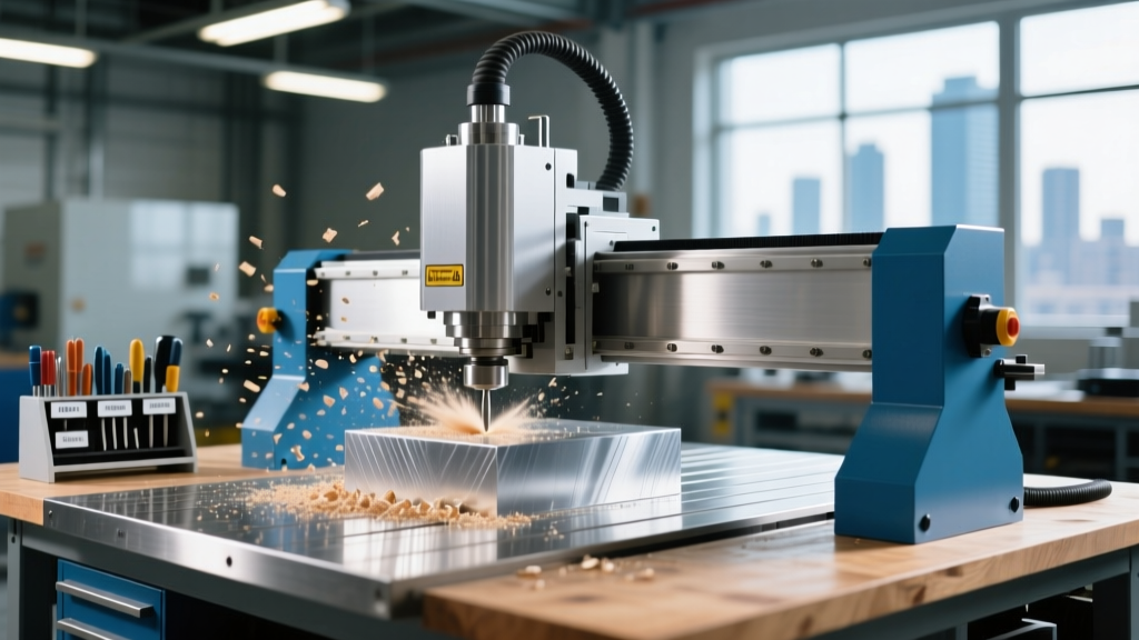
When evaluating CNC machine bed size and work envelope comparisons, manufacturers frequently overlook the fluid dynamics required to maintain thermal stability and chip evacuation. As of 2026, the integration of computational fluid dynamics (CFD) into machine tool design has revealed a critical flaw in legacy flood systems: the aerodynamic umbrella effect. In machines with expansive work envelopes—such as the Haas UMC-1000SS with its 1000 x 762 x 610 mm capacity—standard low-pressure flood cnc machine coolant bounces off the spinning tool holder, creating an air shield that prevents fluid from reaching the cutting edge in deep Z-axis pockets.
Conversely, in compact micro-milling envelopes like the DMG MORI DMU 50 3rd Gen (500 x 450 x 400 mm), high-volume flood delivery causes thermal shock to the carbide substrate and rapidly degrades the cutting edge due to extreme temperature cycling. The physical dimensions of the machine bed directly dictate the required nozzle velocity, pump displacement, and sump ecology management. Upgrading your fluid delivery architecture based on your specific work envelope is no longer optional for shops machining aerospace titanium or Inconel; it is a baseline requirement for tool life optimization.
2026 Data Highlight: Pressure Decay Over DistanceTesting on 5-axis machining centers reveals that a standard 300 PSI (20 bar) coolant pump loses up to 45% of its localized cutting-edge pressure when the Z-axis extends beyond 600mm. To maintain a 1000 PSI effective cutting pressure in large-bed horizontal boring mills, shops must now utilize 1500 PSI (103 bar) through-spindle variable frequency drive (VFD) pumps to compensate for distance-based pressure decay.
Small vs. Large Work Envelopes: A Coolant Delivery Matrix
Matching your cnc machine coolant delivery system to the physical bed size ensures optimal chip evacuation and prevents recutting. Below is a comparison matrix detailing the engineering requirements across three distinct machine classes prevalent in modern job shops.
| Machine Class & Model | Work Envelope (X, Y, Z) | Optimal Delivery Method | Required Pressure / Flow | Sump & Skimmer Sizing |
|---|---|---|---|---|
| Compact 5-Axis (DMG MORI DMU 50) |
500 x 450 x 400 mm | Targeted MQL or Programmable Precision Nozzles | 70 bar / 15 GPM | 40 Gallon / 4-inch tube skimmer |
| Standard Vertical (Haas VF-4SS) |
1270 x 508 x 635 mm | Flood + Through-Tool (Standard) | 20 bar / 45 GPM | 95 Gallon / 8-inch belt skimmer |
| Large Multitasking (Mazak INTEGREX i-800) |
1500 x 800 x 900 mm | High-Pressure Through-Spindle + Z-Tracking Nozzles | 103 bar / 80+ GPM | 250+ Gallon / 12-inch dual belt skimmer |
Sump Ecology: How Bed Surface Area Destroys Coolant pH
A non-obvious consequence of scaling up to a larger CNC machine bed is the accelerated degradation of cnc machine coolant chemistry. Larger work envelopes require significantly more way lube and spindle oil to maintain the precision of extended linear guideways and massive ball screws. This excess lubricant inevitably washes into the machine sump, creating tramp oil.
Tramp oil forms a barrier on the coolant surface, cutting off oxygen and creating an anaerobic environment where sulfate-reducing bacteria thrive. This drops the coolant pH below 8.0, leading to machine corrosion and foul odors. According to Modern Machine Shop, maintaining fluid integrity in large-envelope machines requires aggressive mechanical separation.
- Small Beds (Under 600mm X-axis): A standard 4-inch tube skimmer running 4 hours a day is typically sufficient to manage way lube wash-off.
- Large Beds (Over 1200mm X-axis): The massive surface area of the casting and the volume of the sump demand a 12-inch continuous belt skimmer paired with an automatic tramp oil coalescer. Without this, shops machining on large-bed horizontals will see their coolant concentration fluctuate wildly, requiring weekly sump dumps that cost upwards of $1,500 in fluid replacement and hazardous waste disposal fees.
The MQL Limitation: Aerosol Dissipation in Deep Envelopes
Minimum Quantity Lubrication (MQL) has been heralded as the future of sustainable machining, but it faces strict physical limitations dictated by the work envelope. MQL relies on atomizing microscopic droplets of biodegradable ester oil and delivering them via compressed air through the spindle.
"While MQL excels in shallow, high-speed aluminum milling, attempting to use aerosol delivery in a Z-axis envelope exceeding 800mm results in severe droplet coalescence. The mist loses its kinetic energy before reaching the deep-pocket cutting zone, leading to catastrophic tool welding in titanium applications."
— Adapted from Sandvik Coromant's MQL guidelines
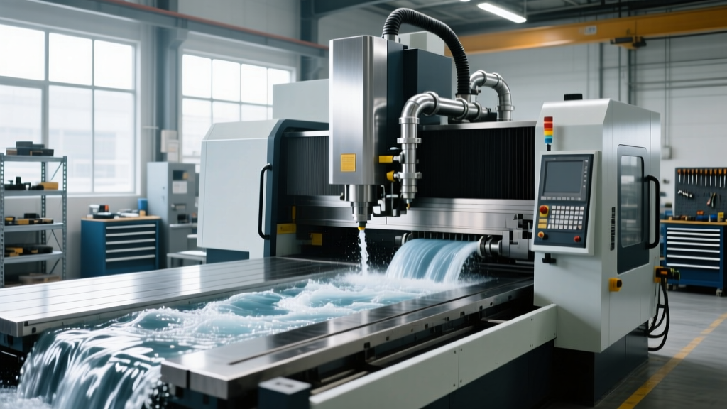
For machines with deep Y-axis and Z-axis travels, high-pressure liquid cnc machine coolant remains mandatory. The liquid stream maintains cohesion over long distances, ensuring the fluid penetrates the shear zone even when the tool is extended 24 inches from the spindle face.
G-Code Synchronized Coolant Mapping (2026 Innovation)
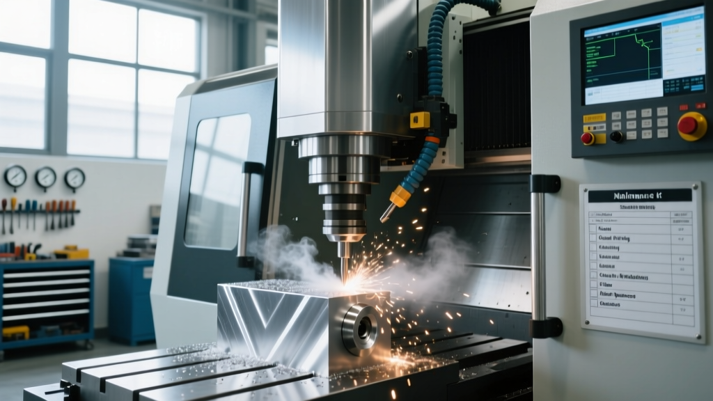
The latest innovation bridging the gap between bed size and fluid delivery is G-code synchronized coolant mapping. In large 5-axis envelopes, fixed flood nozzles are entirely ineffective because the tool vector constantly changes, blocking the fluid path.
Modern controllers now utilize programmable coolant nozzles that read the active Z-axis coordinate and tool length offset in real-time. As the Z-axis retracts in a large work envelope, servo-driven nozzle arrays physically tilt downward to maintain a direct line of sight to the cutting edge. This eliminates the need for manual nozzle adjustments and ensures that the high-pressure stream tracks the tool tip regardless of where it is positioned within the massive 1000mm+ cubic envelope.
Actionable Upgrade Framework for Shop Floors
If your shop is experiencing premature tool wear or poor surface finishes on machines with large work envelopes, execute this 4-step audit to align your fluid delivery with your machine's physical geometry:
- Map the Z-Axis Shadow: Run a dry cycle with a dye-marker attached to the coolant nozzle. Identify the exact Z-depth where the fluid stream is deflected by the tool holder or spindle face. This is your 'shadow zone' where high-pressure through-tool delivery must take over.
- Audit Pump Displacement vs. Hose Diameter: Large beds require long coolant hose runs. If you are running a 1000 PSI pump through standard 1/2-inch hoses over a 6-foot distance, friction loss will rob you of 30% of your pressure. Upgrade to 3/8-inch high-pressure hydraulic lines for the final delivery stage to maintain velocity.
- Right-Size the Skimmer: Measure your sump surface area. Allocate 1 inch of skimmer belt width for every 3 square feet of sump surface area to effectively manage way lube ingress on large-bed machines.
- Implement VFD Pump Logic: Work with your machine OEM to map the coolant pump's Variable Frequency Drive to the spindle load meter. When cutting air during rapid traverses across a large bed, the pump should drop to 15% capacity, saving energy and reducing fluid aeration before ramping back to 100% upon material engagement.
By treating cnc machine coolant not as a static consumable, but as a dynamic system that must scale with the physical dimensions of the work envelope, manufacturers can unlock massive gains in tool life, surface finish, and overall equipment effectiveness (OEE) in 2026 and beyond.