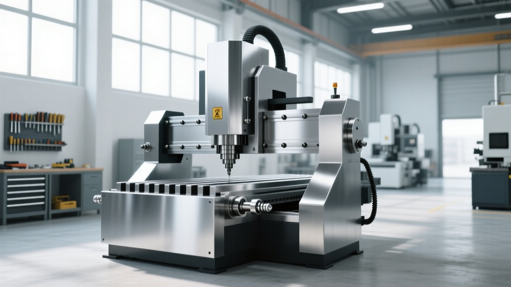
Beyond the Basic of CNC Machine Setup: 2026 Power Trends
Explore 2026 smart electrical requirements for CNC machines. Learn about active harmonic filters, IoT power monitoring, and precise load calculations.
The Evolution of CNC Power Architecture in 2026
While understanding the basic of CNC machine operation is essential for machinists, facility engineers must look far beyond the control panel to ensure uptime. The modern manufacturing floor is no longer just a collection of isolated tools; it is a highly integrated, data-driven ecosystem. In 2026, electrical power setup for Computer Numerical Control (CNC) equipment has shifted from simple 3-phase voltage drops to intelligent, actively monitored power architectures.
Legacy setups relied on oversized isolation transformers and brute-force circuit breakers to handle the massive inrush currents of spindle motors. Today, the integration of Active Front-End (AFE) drives, regenerative braking modules, and edge-computed power quality monitoring has fundamentally changed how electrical infrastructure is designed for machining centers. According to the U.S. Department of Energy Advanced Manufacturing Office, modern motor systems equipped with smart power electronics can reduce facility-wide energy consumption by up to 18%, provided the electrical supply is engineered to support bidirectional power flow and strict harmonic limits.
Calculating True Power Requirements: Beyond the Nameplate
The most frequent point of failure in new CNC installations is sizing the electrical feed based solely on the machine’s nameplate kVA rating. Nameplate data represents a nominal continuous load, completely ignoring the transient inrush currents generated when spindle drives and coolant pumps engage simultaneously.
To prevent nuisance tripping and voltage sags that trigger sensitive control alarms (such as Fanuc SV0401 or Siemens 840D DC link low-voltage faults), engineers must calculate the true peak demand. This requires applying a 125% continuous load multiplier to the base kVA, plus an additional inrush allowance for the largest spindle motor.
2026 Standard CNC Power Sizing Matrix
| Machine Model | Control System | Nameplate kVA | Peak Inrush (Amps) | Recommended Transformer (kVA) | Feed Wire Size (Cu, 75°C) |
|---|---|---|---|---|---|
| Haas VF-2SS | Haas / Fanuc | 35 kVA | 120A | 45 kVA | 3 AWG |
| DMG MORI CMX 600V | Siemens 840D | 52 kVA | 180A | 75 kVA | 1/0 AWG |
| Mazak INTEGREX i-200 | Mazatrol SmoothAi | 65 kVA | 210A | 90 kVA | 2/0 AWG |
| Okuma GENOS M560V | OSP-P300M | 40 kVA | 145A | 55 kVA | 2 AWG |
Note: Wire sizing assumes a maximum 3% voltage drop over a 100-foot run. For longer runs, increase wire gauge by one size per additional 50 feet.
Mitigating Harmonics and Voltage Sags
Modern CNC spindle drives utilize high-frequency Pulse Width Modulation (PWM) switching, which inherently generates Total Harmonic Distortion (THD) back into the facility’s electrical grid. If left unmitigated, this harmonic pollution causes overheating in facility transformers, degrades power factor, and can corrupt the data lines of neighboring IoT sensors.
⚠️ Critical Warning: The Cost of Ignoring IEEE 519 StandardsThe IEEE 519 standard recommends keeping voltage THD below 5% at the Point of Common Coupling (PCC). Facilities that ignore this and operate multiple 5-axis CNC mills without filtration frequently experience premature failure of facility HVAC compressors and LED lighting drivers, resulting in $15,000 to $40,000 in collateral equipment replacement costs annually. Always install 3% or 5% line reactors at the CNC disconnect switch as a baseline defense.
For advanced setups utilizing regenerative spindle drives (which feed braking energy back into the grid), passive line reactors are insufficient. Engineers must deploy Active Harmonic Filters (AHF). A 100A AHF unit typically costs between $4,500 and $7,200 but dynamically injects opposing currents to cancel out harmonics in real-time, maintaining a near-unity power factor (0.98+) and eliminating utility penalty charges.
Smart Power Monitoring & IoT Edge Integration
The most significant innovation in 2026 CNC electrical setups is the integration of edge-computed power quality analyzers directly into the machine’s main disconnect enclosure. Rather than relying on utility meters, facilities are installing Class 0.1S power meters (such as the Siemens SENTRON PAC4200 or Schneider PowerLogic PM5560) to monitor micro-second voltage sags, swells, and transients.
As highlighted in research by NIST Smart Manufacturing Systems, tying power quality data directly to the CNC’s MTConnect interface allows predictive maintenance algorithms to correlate specific voltage anomalies with surface finish defects or premature spindle bearing wear.
Step-by-Step: Commissioning an IoT Power Monitor
- Install the Metering Hardware: Mount the power analyzer in the CNC’s primary 480V disconnect panel. Ensure Current Transformers (CTs) are rated for at least 150% of the machine's maximum continuous current to prevent saturation during inrush events.
- Configure the Sampling Rate: Set the analyzer to capture waveform data at a minimum of 1024 samples per cycle (61,440 samples/second on a 60Hz grid). This resolution is required to capture high-frequency transients caused by neighboring welding equipment or large VFDs starting.
- Establish Alarm Thresholds: Program the edge gateway to trigger an MTConnect alarm if voltage sags exceed 8% for longer than 20 milliseconds, or if THD spikes above 6%.
- Integrate with the CNC Controller: Map the power analyzer’s digital output relays to the CNC’s external emergency stop (E-Stop) or feed-hold circuits. This allows the machine to safely pause the cutting cycle during a severe brownout, preventing tool breakage and scrap parts.
Grounding and Shielding: The Foundation of Signal Integrity
A pristine power supply is useless if the grounding infrastructure introduces noise into the CNC’s low-voltage DC control circuits. High-frequency noise from VFDs and servo drives travels along the ground path, causing erratic axis movements and false limit-switch alarms.
- Impedance Targets: The grounding electrode system for a modern CNC cell must measure less than 1.0 ohm of resistance. For ultra-precision machines (like jig borers or 5-axis aerospace mills), target < 0.5 ohms.
- Connection Methods: Do not rely on mechanical clamps for grounding rods. Use exothermic welding (e.g., Cadweld) to fuse the copper grounding conductor to the rod. Mechanical clamps loosen over time due to thermal expansion and soil shifting, increasing impedance.
- Equipotential Grounding Grid: Install a copper mesh or heavy copper busbar beneath the machine foundation. Bond the machine base, the chip conveyor, the coolant tank, and the control cabinet to this single-point ground grid using a minimum of 4 AWG bare copper wire to prevent ground loops.
- Cable Shielding: All encoder and resolver cables running between the servo drives and motors must utilize double-shielded (foil + copper braid) cables. The shield must be grounded at the drive end only, utilizing a 360-degree shield clamp rather than a pigtail wire, which acts as an antenna at high frequencies.
Final Commissioning Checklist for Facility Engineers
Before energizing a new CNC machine in 2026, verify the following critical electrical parameters to ensure warranty compliance and operational stability:
- [ ] Phase rotation verified (L1-L2-L3) using a digital phase meter; incorrect rotation will instantly destroy coolant pump impellers and hydraulic power units.
- [ ] Incoming voltage measured under full facility load; variance between phases must not exceed 2% (e.g., on a 480V system, no phase should drop below 470V or exceed 490V relative to the others).
- [ ] All busbar and lug connections torqued to manufacturer specifications using a calibrated digital torque wrench; apply thermal indicating paste to monitor for hot spots during the first 48 hours of operation.
- [ ] Control cabinet climate control verified; internal temperature must remain between 20°C and 35°C, with relative humidity strictly maintained below 60% to prevent condensation on I/O boards.
- [ ] Megger testing (insulation resistance) completed on all incoming feed conductors at 1000V DC; minimum acceptable reading is 100 Megohms.
By treating the electrical power setup as an intelligent, actively managed subsystem rather than a static utility feed, manufacturers can drastically reduce unplanned downtime, extend the lifespan of multi-million-dollar spindle assemblies, and secure the precision required for next-generation manufacturing.