Small Workshop CNC Machine Problems and Solutions: Real Case Studies
Explore real-world small workshop CNC machine problems and solutions through detailed case studies on chatter, dust ingress, and thermal drift.
The Reality of Small-Shop CNC Machining
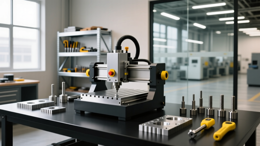
Operating a CNC machine in a small workshop environment—typically defined as under 2,000 square feet with single-phase power and limited climate control—introduces a unique set of mechanical and environmental constraints. Unlike production facilities where 5,000-pound machines sit on isolated concrete slabs in temperature-regulated rooms, small job shops must extract precision from lighter, benchtop, or compact vertical mills placed in multi-use garages or shared spaces.
Analyzing real-world cnc machine problems and solutions in these environments reveals that the root causes of scrapped parts rarely stem from operator error alone. Instead, they originate from structural resonance, microscopic particulate ingress, and ambient thermal shifts. Below are three detailed case studies diagnosing and resolving the most persistent issues faced by small-shop machinists using popular compact platforms like the Tormach 1100MX, ShopBot Desktop MAX, and Syil X7.
Case Study 1: Structural Resonance and Chatter on the Tormach 1100MX
The Problem: Harmonic Chatter in 6061-T6 Aluminum
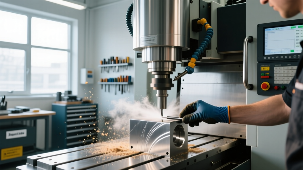
A custom motorcycle parts fabricator operating out of a two-car garage utilized a Tormach 1100MX (BT30 spindle, 7,500 RPM max) to pocket 6061-T6 aluminum brackets. When using a standard 1/2-inch 3-flute carbide end mill at 4,200 RPM and a 0.250-inch radial depth of cut, the machine exhibited severe harmonic chatter. This resulted in a poor surface finish (Ra > 125 µin) and premature tool edge chipping. The 1100MX weighs approximately 1,100 lbs, a fraction of the mass found in a Haas Mini Mill (approx. 4,500 lbs), making its natural frequency highly susceptible to excitation at specific spindle speeds.
The Solution: Variable Helix Tooling and Base Damping
To resolve this without upgrading to a heavier, 3-phase machine, the shop implemented a two-pronged approach targeting both the cutting dynamics and the machine's structural damping.
- Toolpath and Tooling Adjustment: The shop switched to a 1/2-inch 4-flute variable helix end mill (such as the Harvey Tool 79416). The variable helix design breaks up the harmonic frequency by ensuring the cutting edges engage the material at irregular intervals, effectively canceling out the resonant vibration. Spindle speed was increased to 6,800 RPM, moving the excitation frequency away from the machine's natural harmonic node.
- Epoxy Granite Base Fill: To increase the mass and damping coefficient of the machine base, the hollow cast-iron stand was filled with an epoxy granite composite. The mixture consisted of 85% graded silica quartz (ranging from fine sand to 3/8-inch gravel) and 15% two-part liquid epoxy resin. This modification increased the base mass by 140 lbs and improved the vibration damping ratio by nearly 800%, absorbing high-frequency spindle harmonics before they could transfer to the workpiece.
| Spindle Speed (RPM) | Radial DOC (in) | Chatter Severity | Surface Finish (Ra) |
|---|---|---|---|
| 3,200 | 0.250 | High (Audible Ring) | 140 µin |
| 4,200 | 0.250 | Severe (Tool Deflection) | 210 µin |
| 6,800 (Var. Helix) | 0.250 | None | 32 µin |
Case Study 2: Particulate Ingress and Electronics Failure on Wood/Composite Routers
The Problem: MDF Dust Destroying Linear Guides and Drivers
A small architectural model-making shop running a ShopBot Desktop MAX primarily cut Medium Density Fiberboard (MDF) and carbon-fiber-reinforced polymers (CFRP). Within six months, the Y-axis ball screws developed severe pitting, and the NEMA 23 stepper motor drivers began experiencing intermittent short-circuit faults, resulting in lost steps and scrapped prototypes.
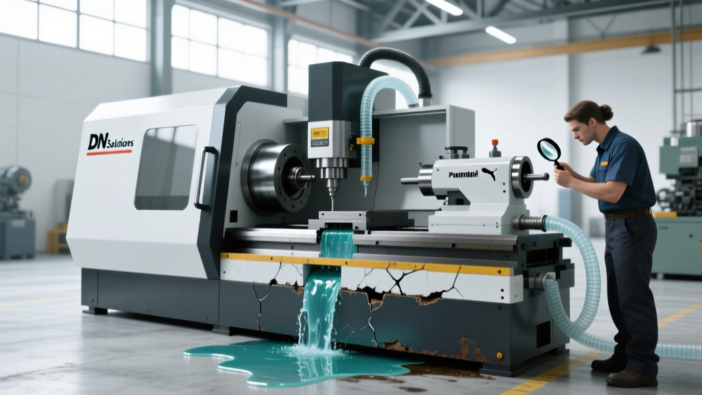
The root cause was twofold. First, MDF dust contains urea-formaldehyde resins. When this microscopic dust mixes with ambient humidity in an unsealed garage, it forms a mildly acidic, highly conductive sludge. This sludge infiltrated the open ball screw nuts and shorted the exposed terminals on the stepper drivers. Second, CFRP dust is essentially microscopic carbon fiber—highly abrasive and electrically conductive—which accelerated the mechanical wear on the unsealed linear rails.
The Solution: Sealed Drivetrains and Positive Pressure Enclosures
The shop overhauled its environmental protection protocols, focusing on isolating the mechanical and electrical components from the cutting envelope.
- Drivetrain Upgrades: The open ball screws were replaced with sealed Acme lead screws equipped with polymer nuts, which are impervious to fine dust ingress and do not require wet lubricants that attract particulates. The linear guides were upgraded to THK sealed carriages with front and side scrapers.
- Positive Air Pressure Bellows: Rather than relying solely on way covers, the shop installed a low-PSI positive air pressure system. A small 12V diaphragm pump feeds filtered air into accordion-style way bellows. This creates a continuous outward airflow, preventing abrasive dust from settling on the rails even when the bellows compress during rapid traverses.
- IP65 Electronics Enclosure: The stepper drivers and breakout boards were relocated from the machine gantry to a sealed NEMA 4X enclosure mounted on the wall, cooled via a closed-loop Peltier thermoelectric cooler rather than a fan that would draw in shop dust.
Case Study 3: Thermal Growth and Tolerance Drift in Unclimate-Controlled Spaces
The Problem: Z-Axis Drift on the Syil X7
A precision instrument repair shop operating a Syil X7 small vertical mill in an uninsulated metal building faced a baffling issue: bore tolerances machined at 8:00 AM were consistently 0.0025 inches deeper than identical bores machined at 3:00 PM. The shop was holding tolerances of ±0.0005 inches for press-fit bearing housings, and the afternoon parts were failing quality control.
The building's ambient temperature shifted from 55°F (12.7°C) in the morning to 78°F (25.5°C) in the afternoon. The Syil X7 features a cast-iron Z-axis column. Cast iron has a Coefficient of Thermal Expansion (CTE) of approximately 10.4 µm/m·°C. Over a 600mm (0.6m) Z-axis column length, a 12.8°C temperature increase results in a linear expansion of roughly 0.079mm (0.0031 inches). Because the spindle head moves down relative to the expanding column, the tool effectively 'grows' into the workpiece as the day warms up.
The Solution: Macro-Driven Thermal Compensation
Rather than spending $20,000 to climate-control the entire metal building, the machinist implemented a software-based thermal compensation strategy using the machine's Mach4 controller.
- Hardware Integration: A digital thermistor was epoxy-mounted directly to the cast-iron Z-column, wired into an analog-to-digital input on the CNC controller's breakout board to read real-time column temperature.
- G-Code Macro Implementation: A custom M-code macro was written to calculate the thermal growth based on the delta between the morning baseline temperature and the current temperature, dynamically adjusting the Z-axis tool length offset.
Base_Temp = 55.0Current_Temp = Read_Thermistor_Input()Delta_T = Current_Temp - Base_TempColumn_Length_mm = 600.0CTE_Cast_Iron = 0.0000104Z_Growth_mm = Delta_T * Column_Length_mm * CTE_Cast_IronApply_Tool_Length_Offset_Adjustment(-Z_Growth_mm)
By applying a negative Z-offset adjustment that scales linearly with the column's temperature, the machine automatically retracts the spindle by the exact amount the cast iron expands, holding the 0.0005-inch tolerance regardless of the time of day. For further reading on thermal stability in CNC operations, Harvey Tool's technical support resources highlight how thermal expansion affects not just the machine castings, but the cutting tool itself, necessitating consistent coolant application to maintain tool length stability.
Diagnostic Matrix: Small Workshop CNC Troubleshooting
When diagnosing small workshop CNC machine problems and solutions, use this matrix to isolate the root cause before replacing expensive components.
| Symptom | Common Misdiagnosis | Actual Small-Shop Root Cause | Targeted Solution |
|---|---|---|---|
| Intermittent lost steps on Y-axis | Failing stepper motor | Conductive dust shorting driver dip-switches | Seal drivers in NEMA 4X enclosure; install positive-pressure way covers. |
| Poor surface finish in aluminum | Dull tooling or bad feeds/speeds | Machine base harmonic resonance at specific RPM | Map FRF with tap test; use variable helix end mills; fill base with epoxy granite. |
| Z-axis depth varies by time of day | Slipping ball screw nut or backlash | Ambient thermal expansion of cast-iron column | Implement temperature-tracking Z-offset macros; run 15-min spindle warm-up cycle. |
| Spindle stalls under heavy load | Broken drive belt or bad VFD | Voltage drop from shared single-phase shop power | Install a dedicated 240V line with a buck-boost transformer; isolate from welders/compressors. |
Strategic Takeaways for Small Shop Owners
Solving CNC issues in constrained environments requires looking beyond the machine's manual. Small workshop CNC machine problems and solutions are inherently tied to the building's infrastructure, the specific materials being cut, and the ambient environment. By investing in structural damping, implementing aggressive particulate isolation, and leveraging controller macros for thermal compensation, small job shops can achieve production-grade tolerances on compact, budget-friendly machinery.