Robot CNC Machine Controllers: Operator Training and Interface Guide
Master robot CNC machine controllers with this operator training guide. Compare Siemens, FANUC, and KUKA interfaces, TCP calibration, and safety protocols.
The Kinematic Divide: Why Robot CNC Controllers Demand New Skills
Operating a robot CNC machine requires fundamentally unlearning the rigid assumptions of traditional 3-axis and 5-axis vertical machining centers (VMCs). While a standard CNC relies on Cartesian kinematics—where X, Y, and Z movements are linear and independent—a 6-axis robotic arm operates in joint space. When an operator commands a linear toolpath via G-code, the robot CNC machine controller must continuously calculate inverse kinematics to coordinate six rotary joints simultaneously. This architectural difference dictates everything from toolpath planning to chatter management.
Modern hybrid manufacturing integrates subtractive precision with robotic flexibility, but the interface between the CAD/CAM environment and the physical arm is where most production bottlenecks occur. According to research on flexible manufacturing systems published by the National Institute of Standards and Technology (NIST), the primary failure mode in robotic machining is not mechanical failure, but kinematic misalignment and improper feedrate mapping at the controller level. Operators must transition from thinking in terms of 'machine coordinates' to 'work object frames' and joint singularities.
⚠️ CRITICAL WARNING: Singularity TrapsUnlike a 5-axis CNC trunnion table, a 6-axis robot CNC machine will encounter kinematic singularities—poses where the robot loses a degree of freedom and joint velocities spike toward infinity. If an operator runs a continuous G01 linear move through a singularity zone without joint-interpolation blending, the controller will trigger an emergency stop, potentially leaving a deep gouge in the workpiece and damaging the spindle bearings.
Controller Interface Comparison Matrix
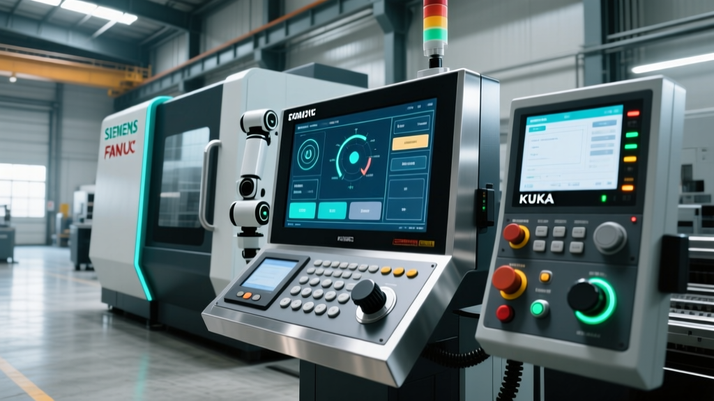
Selecting the right controller ecosystem dictates the training pathway for your operators. The three dominant architectures in the robot CNC machine space handle G-code translation and kinematic compensation differently. Below is a technical comparison of the primary interfaces operators will encounter on the shop floor.
| Controller Ecosystem | Native G-Code Execution | Post-Processor Cost | Kinematic Handling | Operator Learning Curve |
|---|---|---|---|---|
| Siemens SINUMERIK ONE (Run MyRobot) | Native (Identical to standard CNC) | $8,000 - $12,000 | Transforms robot into a virtual CNC axis; handles singularities via TRAORI. | Moderate (Familiar to VMC operators) |
| KUKA KR C5 (KUKA.CNC) | Native via integrated interpreter | $10,000 - $15,000 | Maps G-code to KRL (KUKA Robot Language); requires strict WObj definition. | High (Requires dual CNC/Robot knowledge) |
| FANUC R-30iB Plus (Robomachining) | Requires specific G-code dialect | $12,000 - $18,000 | Uses standard FANUC CNC interface but limits 6-axis simultaneous blending. | Moderate to High |
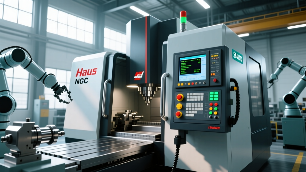
For facilities adopting the Siemens SINUMERIK ONE architecture, operators benefit from a unified HMI. The Run MyRobot software essentially masks the robotic arm as a standard 5-axis machine, allowing operators to use familiar cycles like CYCLE83 for drilling. Conversely, KUKA.CNC requires operators to understand both standard G-code and the underlying KUKA Robot Language (KRL) to troubleshoot fault codes effectively.
Step-by-Step Operator Training Protocol
A robust training program for a robot CNC machine must prioritize physical calibration and dynamic stiffness management over simple G-code syntax. Use this phased protocol to certify operators.
Phase 1: Tool Center Point (TCP) Mastery
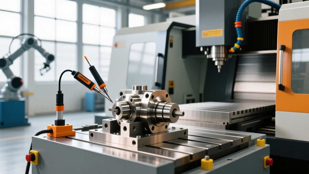
The TCP is the exact point in space where the cutting tool interacts with the material. Because robotic arms suffer from thermal expansion and payload deflection, TCP calibration must be performed at the start of every shift, not just during initial setup.
- The 4-Point Method: Instruct operators to use a fixed calibration spike mounted to the robot base. The operator must jog the tool tip to the spike from four distinctly different approach vectors (varying the A, B, and C rotational axes by at least 30 degrees between points).
- Tolerance Verification: The controller calculates the TCP intersection. The maximum allowable error for machining operations is 0.05 mm. If the controller reports an error of 0.12 mm, the tool must be reseated in the collet, and the calibration repeated. A 0.10 mm TCP error will result in severe gouging during 5-axis simultaneous contouring.
- Payload Compensation: Operators must input the exact weight and center of gravity (COG) of the spindle and tool holder into the controller's payload data screen. Failing to update this when switching from a 2kg face mill to a 5kg roughing tool will cause the robot's gravity compensation algorithms to fail, leading to Z-axis droop.
Phase 2: Work Object (WObj) Frame Alignment
Unlike a VMC where the part is bolted to a fixed table, a robot CNC machine often machines parts held in custom fixtures or even on secondary rotary positioners. Operators must define the WObj frame using a 3-point method (Origin, X-direction, Y-direction) directly on the physical fixture. This ensures that if the fixture is bumped or moved, the operator only needs to re-teach the WObj frame rather than reprogramming the entire toolpath.
Phase 3: Managing Dynamic Stiffness and Chatter
This is the most critical divergence from standard CNC training. A cast-iron VMC possesses a dynamic stiffness of roughly 200 to 300 N/μm. A heavy-duty 6-axis machining robot possesses a dynamic stiffness of only 1 to 5 N/μm, depending on the arm's extension. Operators must be trained to adjust CAM parameters accordingly:
- Radial Depth of Cut (RDOC): Must be reduced by 60% to 80% compared to VMC operations to prevent tool deflection and chatter.
- Spindle Speed Tuning: Operators must use tap-testing or acoustic monitoring to identify the chatter frequency of the robot in its specific pose, adjusting spindle RPM to avoid harmonic resonance.
- Climb vs. Conventional: Strictly enforce climb milling. Conventional milling pushes the tool away from the cut, and the robot's lack of rigidity will cause the tool to 'grab' and violently deflect.
'The biggest mistake we see in robotic machining is operators treating the robot like a VMC with a longer reach. When you extend a 2-meter robotic arm to its maximum reach, the stiffness drops exponentially. Operators must learn to reposition the workpiece closer to the robot's base envelope rather than stretching the arm to reach the far edge of a large mold.'
— Lead Applications Engineer, Advanced Robotic Machining Integration
Troubleshooting Common Controller Faults
When the robot CNC machine halts production, operators must quickly diagnose whether the fault is mechanical, kinematic, or related to the G-code translation. Below is a decision matrix for the three most common interface errors.
- Error: 'Axis Limit Exceeded during G02/G03'
Cause: The programmed arc requires a joint to rotate past its physical hard limit (e.g., Joint 4 exceeding ±185°).
Fix: Do not simply edit the G-code. Open the controller's 3D simulation, identify the joint limit violation, and shift the WObj frame 150mm closer to the robot base to alter the inverse kinematic solution. - Error: 'Interpolation Velocity Limit'
Cause: The programmed feedrate (e.g., F3000) requires a joint to accelerate faster than its servo motor allows, usually occurring during tight cornering or small-radius arcs.
Fix: Implement 'Look-Ahead' blending parameters in the controller. Reduce the exact-stop (G61) commands and replace them with continuous-path blending (G64) with a defined tolerance band (e.g., G64 P0.1) to allow the controller to smooth the joint velocities. - Error: 'Spindle Load Spike / Torque Limit'
Cause: Tool deflection due to arm posture. The robot is in a low-stiffness configuration (e.g., elbow fully extended).
Fix: Pause the cycle. Jog the robot to a more compact, 'elbow-bent' posture, re-teach the WObj frame to match the new base position, and resume. Always prioritize keeping the robot's joints near 90 degrees for maximum rigidity.
Safety Interlocks and Light Curtain Integration
Operating a robot CNC machine introduces severe hazards, primarily due to the large, unpredictable sweep of the arm and the presence of high-speed cutting tools. Safety protocols must adhere to the stringent guidelines established by the Association for Advancing Automation (A3).
Operators must be trained to verify the PROFIsafe or CIP Safety communication loops before initiating any automated cycle. The controller interface must be configured with dual-zone speed limiting:
- Zone 1 (Inner Machining Envelope): Protected by physical interlocked guarding. The robot operates at full programmed feedrates and spindle speeds.
- Zone 2 (Operator Load/Unload Zone): Protected by safety-rated laser scanners or light curtains. If the scanner detects an intrusion, the controller must instantly downgrade the robot's TCP speed to a maximum of 250 mm/s and reduce the spindle speed to zero, while maintaining torque to prevent the tool from dropping.
Operators must perform a weekly validation of the safety stop categories. Using the teach pendant, they should intentionally break the light curtain beam during a simulated dry-run to verify that the controller triggers a Category 0 or Category 1 stop within the required 150-millisecond latency window. Documenting these latency tests in the controller's maintenance log is critical for compliance and ensures the hybrid system remains as safe as it is productive.