What Are CNC Machines? Optimizing Spindle Speed and Feed Rates
Discover what are CNC machines by mastering spindle speed and feed rate optimization. Learn formulas, material matrices, and real-world troubleshooting.
Beyond Basic Automation: The Kinematics of CNC Machining
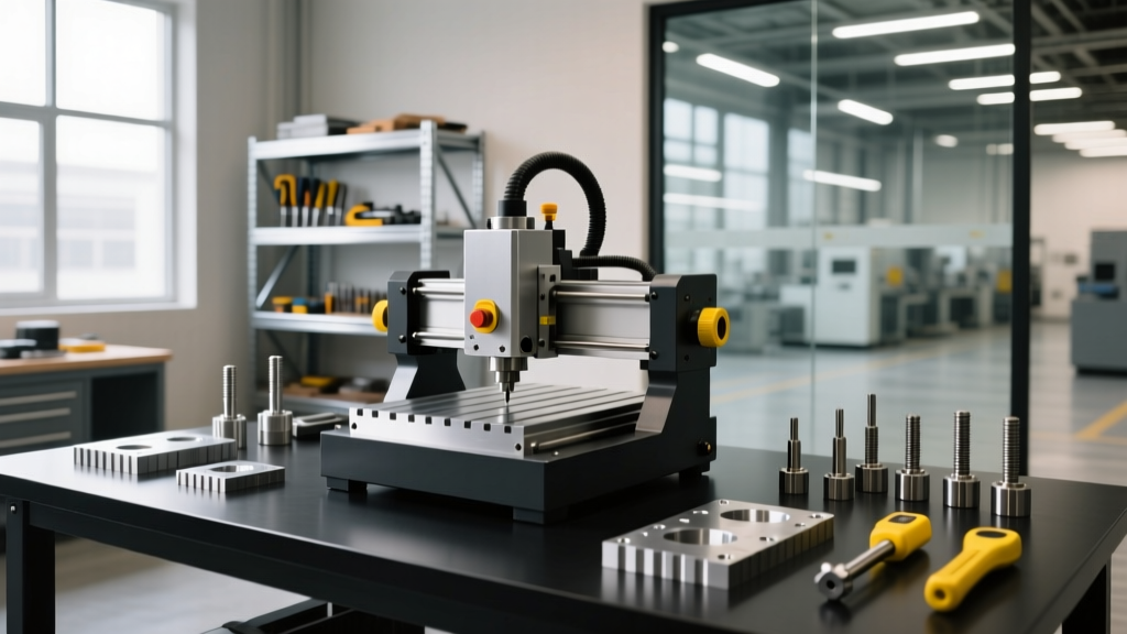
When industry newcomers ask, 'what are CNC machines,' the simplest answer is that they are automated subtractive manufacturing tools. However, from an engineering perspective, CNC (Computer Numerical Control) mills and lathes are precision kinematic systems. The true capability of a machine like a Haas VF-2SS or a DMG MORI CMX 600V is not defined merely by its G-code toolpath, but by the exact synchronization of its spindle speed (RPM) and feed rate (IPM). Optimizing these two variables dictates tool life, surface finish quality, cycle time, and the structural integrity of the machined part.
Misjudging the relationship between spindle rotation and axis travel results in catastrophic tool failure, work hardening of exotic alloys, and severe chatter. To master CNC operation, machinists must transition from relying on generic parameter charts to calculating dynamic speeds and feeds based on real-world cutting mechanics.
The Core Variables: SFM, RPM, IPT, and IPM
Before calculating parameters, it is critical to distinguish between machine-dependent variables and tool-dependent variables. According to Sandvik Coromant's milling guidelines, confusing these metrics is the primary cause of premature insert wear.
- Surface Feet per Minute (SFM) / Surface Speed (Vc): The speed at which the cutting edge engages the material. This is a material-and-tooling constant, independent of the tool diameter.
- Spindle Speed (RPM): The actual rotational speed of the machine spindle required to achieve the target SFM. This is highly dependent on tool diameter.
- Inches Per Tooth (IPT) / Chip Load: The thickness of the material removed by a single cutting flute in one revolution.
- Inches Per Minute (IPM) / Feed Rate: The linear travel speed of the tool or table, dictated by RPM, flute count, and IPT.
The Math Behind the Cut: Calculating Speeds and Feeds
Modern CAM software calculates these values automatically, but manual verification is mandatory to prevent software-generated defaults from destroying tooling. The foundational formulas for imperial milling operations are:
RPM Formula: RPM = (SFM × 3.82) / Tool Diameter (inches)
Feed Rate Formula: IPM = RPM × Number of Flutes × IPT (Chip Load)
Real-World Calculation Example
Assume you are roughing a pocket in 6061-T6 Aluminum using a 0.500-inch diameter, 4-flute solid carbide end mill.
- Determine SFM: For uncoated carbide in 6061-T6, the optimal SFM range is 1,200 to 1,800. We will target 1,500 SFM.
- Calculate RPM: (1,500 × 3.82) / 0.500 = 11,460 RPM.
- Determine IPT: A standard chip load for a 1/2-inch carbide end mill in aluminum is 0.004 inches per tooth.
- Calculate IPM: 11,460 RPM × 4 flutes × 0.004 IPT = 183.36 IPM.
Programming the machine with S11460 and F183 ensures the tool operates within its designed thermal and mechanical limits.
Material-Specific Optimization Matrix
Material properties dictate the baseline SFM and IPT. The following matrix outlines starting parameters for common aerospace and automotive materials using modern CNC toolpaths. For deeper insights into specialty alloy machining, refer to the Kennametal Knowledge Center.
| Material | Tooling Specification | Target SFM Range | Chip Load (IPT) | Coolant Strategy |
|---|---|---|---|---|
| 6061-T6 Aluminum | Uncoated / ZrN Carbide (3-Flute) | 1,200 - 1,800 | 0.003 - 0.006 | Air Blast or Mist |
| 304 Stainless Steel | AlTiN Coated Carbide (4-Flute) | 150 - 250 | 0.001 - 0.002 | High-Pressure Flood |
| Ti-6Al-4V (Grade 5) | PVD Coated Carbide (Variable Helix) | 60 - 90 | 0.0008 - 0.0015 | Through-Tool High-PSI |
| Inconel 718 | SiAlON Ceramic or AlTiN Carbide | 80 - 120 (Carbide) | 0.001 - 0.002 | Flood (Never Air Blast) |
Advanced Edge Cases: Chip Thinning and Radial Engagement
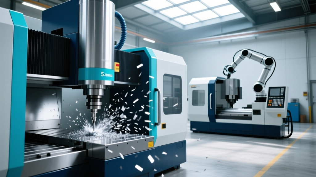
One of the most frequently misunderstood concepts in CNC optimization is chip thinning. When performing high-efficiency milling (HEM) or trochoidal milling, the radial depth of cut (RDOC) is often less than 50% of the tool diameter.
Warning: The Chip Thinning TrapWhen RDOC drops below half the tool diameter, the chip thickness becomes narrower than the programmed IPT. If you do not increase the feed rate to compensate, the cutting edge will 'rub' rather than shear the material. In materials like 304 Stainless or Inconel, rubbing instantly induces work hardening, destroying the end mill and potentially scrapping the part.
To compensate, machinists must apply a chip thinning multiplier. For example, if your RDOC is 10% of the tool diameter, your effective chip load drops by roughly 68%. You must increase your programmed IPM by a factor of 3 to maintain the actual physical chip thickness required for proper heat evacuation. Detailed geometric models for chip thinning are thoroughly documented in Harvey Tool's technical resources.
Climb vs. Conventional Milling Feed Dynamics
The direction of feed relative to spindle rotation fundamentally alters tool wear and surface finish.
Climb Milling (Down Milling)
The tool rotates in the same direction as the feed. The chip starts thick and ends thin. This is the mandatory standard for modern CNC machining because it pushes the cutting forces down into the workpiece, reducing part lift, and allows the chip to carry away the majority of the cutting heat. However, climb milling requires a machine with minimal backlash in the ballscrews; otherwise, the tool will grab the material and chatter.
Conventional Milling (Up Milling)
The tool rotates against the feed direction. The chip starts thin and ends thick. This causes the tool to rub initially before engaging, generating excessive heat and accelerating flank wear. Conventional milling should only be utilized when machining castings with heavy scale or when using older manual machines with significant axis backlash.
Machine Capability Constraints: Matching Code to Hardware
A G-code program optimized for a 20,000 RPM HSC (High-Speed Cutting) machine will fail on a standard 8,000 RPM VMC. Furthermore, spindle speed is only half the equation; axis acceleration dictates real-world cycle times.
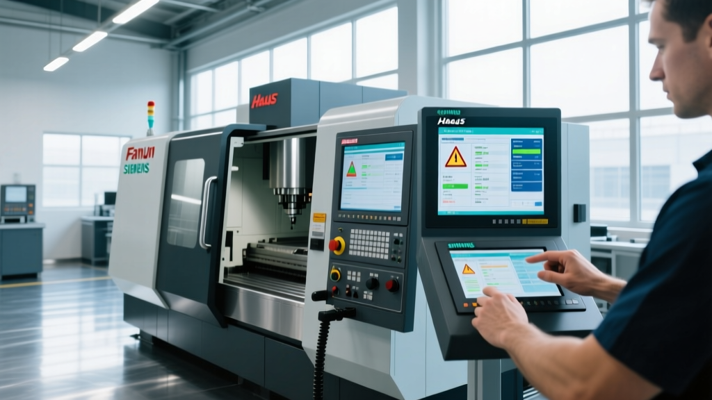
Consider a machine equipped with a Siemens Sinumerik One control. When executing complex 3D contours at high feed rates, the physical mass of the table and saddle limits how fast the servo motors can decelerate and accelerate around tight corners. If the IPM is programmed too high, the control will automatically override the feed rate to prevent overshoot, resulting in dwell marks on the part surface. Utilizing look-ahead algorithms (often 200 to 500 blocks ahead) allows the CNC control to pre-calculate deceleration points, maintaining a constant chip load and protecting the surface finish.
Troubleshooting Poor Surface Finish and Tool Wear
When a process fails, the physical evidence on the tool and the part dictates the necessary adjustment to spindle speed or feed rate.
- Symptom: High-pitch squeal or visible vibration (Chatter).
Cause: Harmonic resonance between the tool overhang and the spindle frequency.
Fix: Alter the RPM by 10-15% up or down to break the harmonic node. Alternatively, switch to a variable helix/variable pitch end mill to disrupt the harmonic frequency. - Symptom: Built-Up Edge (BUE) on aluminum or galling on stainless steel.
Cause: RPM too low or IPT too low, causing the material to weld to the cutting edge rather than shear.
Fix: Increase the SFM (raise RPM) and verify that the chip load exceeds the cutting edge hone radius. Ensure adequate coolant flow to prevent localized welding. - Symptom: Chipped cutting edges or catastrophic flute shearing.
Cause: Feed rate (IPM) is too high for the radial engagement, or the material has hard inclusions.
Fix: Reduce the IPT by 20% and verify the toolpath does not contain full-slotting (100% RDOC) engagements. Implement ramping or helical interpolation for entry moves. - Symptom: Excessive flank wear (uniform wear along the cutting edge).
Cause: Normal abrasive wear accelerated by excessive surface speed.
Fix: Reduce the SFM by 15-20%. While this increases cycle time, it will exponentially extend tool life according to the Taylor Tool Life equation.
Mastering the Variables
Understanding what are CNC machines requires looking past the enclosure and the control screen to the physics of the cutting zone. By rigorously calculating SFM and IPT, compensating for chip thinning during light radial cuts, and matching feed rates to the dynamic acceleration limits of the specific machine hardware, manufacturers can drastically reduce cost-per-part while achieving superior metallurgical surface finishes.