Beyond the Bed: How the Work Envelope of a CNC Machine is Evolving
Discover how the work envelope of a CNC machine is evolving beyond traditional bed sizes. Compare 5-axis, hybrid, and modular envelope innovations.
When evaluating a CNC machine, engineers historically fixated on the X-Y-Z travel limits of the cast-iron bed. A 40-inch by 20-inch table implied a 40x20-inch part capacity. In 2026, this Cartesian assumption is not just outdated; it is a critical liability in multi-axis and hybrid manufacturing. The true metric of capacity is the kinematic work envelope—the actual 3D volumetric space where the tool tip can maintain cutting engagement without collision, factoring in spindle geometry, fixturing, and rotational payload derating.
The Cartesian Illusion and the 30% Envelope Tax
On a standard 3-axis vertical machining center (VMC), the physical bed size is largely negated by the "envelope tax." If a machine features a 50" x 25" bed, the usable work envelope is rarely larger than 35" x 17". This 30% reduction accounts for tool changer clearance, spindle nose overhang, vise footprints, and the necessary safe traverse zones required to prevent rapid-move crashes.
Modern manufacturing trends have shifted focus from maximizing raw bed dimensions to optimizing the spherical sweep volume. In 5-axis machining, the work envelope is not a cube; it is a complex, intersecting geometry dictated by the rotational axes. According to NIST's machining metrology guidelines, volumetric accuracy across this sweep volume is now a more critical purchasing criterion than raw linear travel, as thermal growth and geometric errors compound exponentially at the extreme edges of the rotational envelope.
5-Axis Kinematics: Trunnion vs. Swivel Head Envelopes
The geometry of the work envelope changes drastically depending on whether the machine utilizes a trunnion table (rotating the part) or a swivel head (rotating the spindle). This distinction dictates not just the shape of the envelope, but the mass limits within it.
Trunnion Table Envelopes (A/C or B/C Axis)
In a trunnion setup, the table tilts and rotates. The work envelope forms a spherical or cylindrical intersection. However, the effective payload capacity is not static. When the A-axis tilts to 90 degrees, the gravitational vector shifts entirely, placing maximum stress on the trunnion bearings. A machine rated for a 1,000 lb payload at 0 degrees may safely support only 450 lbs at full tilt.
Swivel Head Envelopes (Head-Head)
Swivel head machines keep the part stationary on a massive, fixed bed while the spindle articulates. The work envelope here is essentially the Cartesian bed size minus the swing radius of the spindle head. This configuration excels in aerospace manufacturing, where large, lightweight structural components (like titanium wing ribs) require vast X-Y travels but do not exceed the tilting payload limits of a trunnion table.
| Machine Model | Kinematic Style | Linear Travels (X-Y-Z) | Effective Spherical Envelope | Max Tilt Payload | Primary Application |
|---|---|---|---|---|---|
| Haas UMC-750 | Trunnion (Integrated) | 30" x 20" x 20" | Ø 19" Sphere | 600 lbs (at 90°) | Job shop, mid-size aerospace |
| DMG Mori DMU 50 3rd Gen | Trunnion (NC Rotary) | 25.6" x 20.5" x 18.5" | Ø 19.7" x 15.7" | 1,320 lbs (0°) / 660 lbs (90°) | High-precision medical, molds |
| Mazak VARIAXIS i-800 NEO | Trunnion (Tilt-Rotary) | 31.5" x 30" x 26" | Ø 31.5" Sphere | 2,200 lbs (0°) / 880 lbs (90°) | Large valve bodies, impellers |
| Klingelnberg H 160 | Swivel Head (Gantry) | 63" x 47" x 31" | 63" x 47" Prism (minus head swing) | 4,400 lbs (Static Table) | Heavy aerospace structural |
Hybrid Additive-Subtractive: The Dual-Purpose Envelope
The most aggressive envelope innovation in 2026 is the integration of Directed Energy Deposition (DED) with subtractive milling. Machines like the Mazak INTEGREX i-400 AM series feature a wire-arc or laser deposition head mounted alongside the milling spindle.
This creates a highly complex, dual-purpose work envelope. The CAM software must map two distinct collision zones: the physical reach of the milling tool holder, and the broader, cone-shaped clearance required for the deposition torch and shielding gas nozzles. The usable subtractive envelope is often 15% smaller than the additive envelope because the milling spindle requires rigid, close-proximity tooling, whereas the DED head can build up geometry from a greater standoff distance. Engineers programming these hybrid machines must utilize sequential envelope mapping—building near-net-shape features in the larger additive zone, then indexing the part into the tighter subtractive zone for final tolerance machining.
Collision Warning in Hybrid Envelopes: When transitioning from additive DED to subtractive milling on a hybrid machine, the deposition head must be fully retracted to its parked position. Failure to validate the parked-head clearance within the digital twin will result in the milling spindle colliding with the DED nozzle during rapid Z-axis traverses, causing upwards of $85,000 in immediate mechanical damage.Parallel Kinematics: Maximizing Envelope Density
While Cartesian and 5-axis trunnion machines dominate the market, Parallel Kinematic Machines (PKMs)—often utilizing hexapod (Stewart platform) designs—are carving out a niche in localized, high-speed 5-axis machining. Instead of stacking linear axes (which compounds geometric error and requires massive floor space), PKMs use six telescoping struts to move the spindle.
The work envelope of a hexapod is not a cube or a simple sphere; it is a complex, convex polyhedron. While the total volumetric capacity is smaller than a traditional VMC, the envelope density is vastly superior. A PKM can achieve full 5-axis simultaneity within a highly compact footprint, maintaining extreme rigidity because the cutting forces are distributed across six struts rather than cantilevered off a single Z-axis column. This makes PKMs ideal for machining complex, deep-cavity features in localized areas of massive parts (such as landing gear forgings) where the part remains stationary on the factory floor and the machine is mounted directly to the workpiece.
AI and Digital Twin Envelope Validation
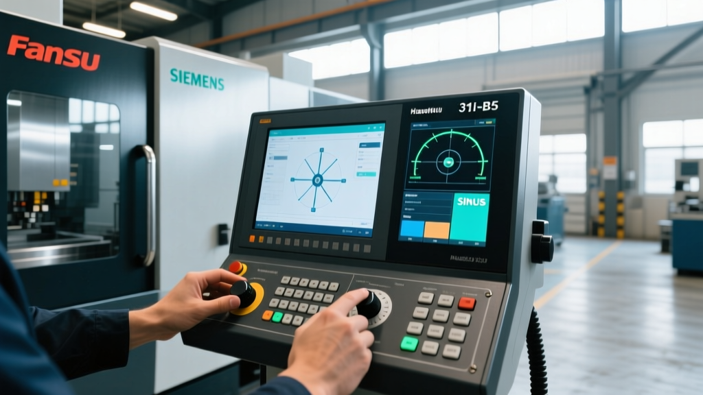
The physical limits of the work envelope are now managed by AI-driven digital twins. In 2026, relying on basic CAM collision detection is considered negligent. Modern CNC controllers integrate real-time kinematic solvers that map the exact physical envelope, including the specific tool holder length, collet nut diameter, and workpiece fixturing.
According to research published by the Society of Manufacturing Engineers (SME), digital twin validation reduces setup-related envelope crashes by 94%. The software calculates the precise sweep volume of the tool assembly at maximum spindle RPM, factoring in the centrifugal expansion of the tool holder and the thermal growth of the spindle nose. If a programmed toolpath exits the validated safe envelope by even 0.005 inches, the controller preemptively halts the feed rate before a collision occurs.
Decision Framework: Specifying the Envelope for Your Application
Do not purchase a machine based on the brochure's X-Y-Z travel numbers. Use this framework to spec the true work envelope:
- Define the Bounding Sphere, Not the Bounding Box: Measure the maximum diagonal of your part, including the vise or fixture. If the diagonal exceeds the machine's published spherical envelope diameter, the part will collide with the machine column during A-axis rotation.
- Calculate the Tilted Payload: Take your heaviest raw billet and fixture weight. Multiply by 2.2 to account for the dynamic G-forces generated during rapid A-axis tilting. If this number exceeds the manufacturer's 90-degree payload rating, you must downgrade to a swivel-head machine.
- Map the Tool Changer Intrusion: On machines with side-mount tool changers, the arm swing intrudes into the negative X-axis envelope. Ensure your tallest fixture does not occupy the Z-clearance zone required for the tool changer arm to rotate.
- Validate with Native CAD: Before signing a purchase order, request the machine manufacturer's native 3D kinematic model (STEP or JT format). Import it into your CAM software alongside your largest intended part and fixture to run a dry-run sweep volume analysis.
The evolution of the CNC work envelope reflects a broader shift in manufacturing: from brute-force material removal to highly orchestrated, multi-axis spatial choreography. By prioritizing kinematic sweep volumes, payload derating, and digital twin validation over static bed dimensions, shops can eliminate costly collisions, maximize spindle uptime, and accurately bid on complex geometries that push the boundaries of modern machining.