9 Axis CNC Machine Controller Interfaces: Operator Training
Best practices for training operators on 9 axis CNC machine controller interfaces, covering Fanuc 31i-B5 and Siemens Sinumerik multi-channel setups.
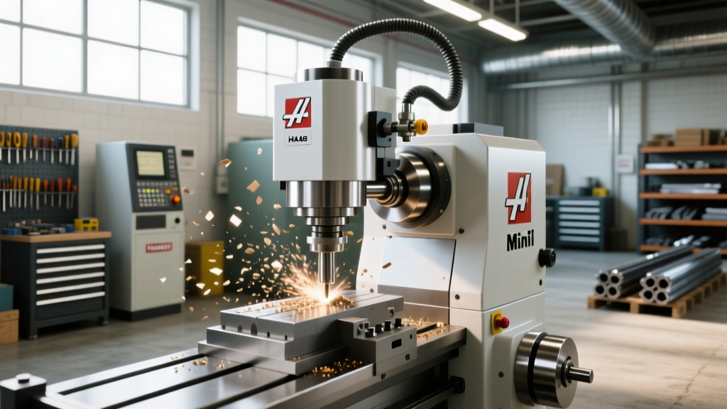
Operating a 9 axis CNC machine requires a fundamental shift from traditional 3-axis milling or 2-axis turning. Modern mill-turn centers, such as the DMG MORI NTX 2000 or Mazak INTEGREX i-Series, pack nine simultaneous axes of motion into a single work envelope. A fully loaded 9-axis configuration routinely exceeds $1.4 million in capital cost. Handing the pendant to an operator trained only on standard vertical machining centers is a guaranteed path to catastrophic spindle crashes.
The complexity does not stem merely from the mechanical axes, but from the multi-channel controller interfaces that govern them. Mastering these interfaces—specifically the Fanuc Series 31i-B5 and the Siemens Sinumerik 840D sl with Operate HMI—is the core objective of advanced operator training. This guide details the exact training modules, synchronization protocols, and interface best practices required to safely and profitably run 9-axis mill-turn equipment in 2026.
Decoding the 9-Axis Architecture
Before an operator touches the HMI (Human-Machine Interface), they must understand how the controller maps the physical machine. A standard 9-axis mill-turn center distributes motion across two primary channels (sometimes three), requiring the controller to interpolate simultaneous linear and rotary movements while managing independent tool paths.
Standard 9-Axis Mapping Protocol:- Channel 1 (Upper Mill/Turn): X1 (Cross), Y1 (Vertical), Z1 (Longitudinal), B1 (Milling spindle tilt), C1 (Main spindle rotation).
- Channel 2 (Lower Turret/Sub): X2 (Lower cross), Y2 (Lower vertical - if equipped), Z2 (Lower longitudinal), C2 (Sub-spindle rotation).
Training must begin with axis verification. Operators should be taught to run slow-feed (<500 mm/min) dry cycles using the machine's manual pulse generator (MPG) to physically verify that the controller's coordinate system matches the physical tool approach vectors, particularly the Y2 and B1 axes, which are the most common culprits for setup errors.
Controller Showdown: Fanuc 31i-B5 vs. Siemens 840D sl
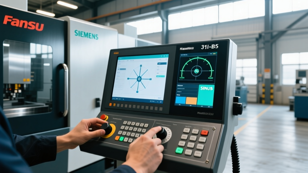
The two dominant controllers in the 9-axis space require distinctly different training approaches. The Fanuc 31i-B5 relies on G-code macro programming and distinct channel switching, while the Siemens 840D sl utilizes a graphical, object-oriented approach via its Sinumerik Operate HMI.
| Feature | Fanuc Series 31i-B5 | Siemens Sinumerik 840D sl |
|---|---|---|
| Multi-Channel Interface | Split-screen mode; requires explicit channel switching (G-code focus). | Unified Operate HMI; simultaneous multi-channel graphical monitoring. |
| 5-Axis Tool Orientation | G43.4 (Tool Center Point Control - TCPC). | TRAORI (Transformation Orientation). |
| Spindle Synchronization | M50 / M51 (with specific spindle selection arguments). | COUPON / COUPOF (Coupling on/off via synchronous actions). |
| Channel Interlocks | WAITM (Wait for channel sync via macro variables). | WAITM (Channel synchronization via integrated PLC commands). |
| Training Learning Curve | Steeper for visual learners; highly logical for G-code veterans. | Faster visual onboarding; requires understanding of Siemens cycles. |
Core Training Modules for Multi-Channel Operators
Effective training programs for 9 axis CNC machine operators must move beyond basic tool offsets and focus heavily on spatial awareness and channel synchronization.
Module 1: Tool Center Point Control (TCPC) and RTCP
When the B1 axis tilts the milling head on a 9-axis machine, the tool tip shifts in space. If the controller does not compensate for this, the tool will gouge the part. Operators must be trained on how the controller handles Rotary Tool Center Point (RTCP) control.
- Fanuc Execution: Train operators to verify that
G43.4 H_is active before any B-axis tilt command. A common fatal error is calling a B-axis move in the same block as the Z-axis plunge before TCPC is fully established. - Siemens Execution: Operators must understand
TRAORI. Training should focus on the difference betweenTRAORI(1)(standard orientation) andTRAFOOF(turning off transformation for specific boring bar operations).
Module 2: Synchronization and Interlocks
In a 9-axis setup, Channel 1 might be rough-milling a turbine blade profile while Channel 2 performs back-working on the sub-spindle. If the sub-spindle attempts to pick off the part from the main spindle before Channel 1 retracts the B1 milling head, a $60,000 collision occurs.
Operators must be trained to read and write synchronization codes. The WAITM function is critical. For example, in a Siemens environment, WAITM(1, 2) forces both Channel 1 and Channel 2 to pause until both have reached that specific line of code. Training should involve deliberately writing flawed sync codes in a simulation environment to demonstrate how the PLC handles interlock faults and how to safely reset the machine without losing absolute position data.
Collision Avoidance via Digital Twin Simulation
Physical dry-runs on a 9 axis CNC machine are insufficient due to the sheer volume of simultaneous movements. Modern operator training mandates the use of integrated digital twins before a single chip is cut.
Warning: The "Trust but Verify" Simulation ProtocolNever assume CAM-generated toolpaths are collision-free on a 9-axis machine. Post-processors often fail to account for the exact physical footprint of the B-axis spindle housing or the lower turret's tool holders. Operators must run the NC code through the controller's native 3D simulation (e.g., Siemens Run MyVirtual Machine or Fanuc Manual Guide i) at 10x speed, specifically watching for B-axis housing interference with the main spindle chuck during extreme Y-axis traversals.
Training budgets should allocate $1,200 to $1,800 per operator for dedicated digital twin software training. An operator who can manipulate the 3D model, isolate specific channels, and view real-time tool clearance maps will reduce setup times by up to 40% compared to operators who rely solely on single-block physical verification.
Ergonomics and HMI Customization
A 15-inch or 19-inch pendant screen is crowded when displaying nine axes of data, active spindle loads, and multi-channel alarms. Best practices dictate training operators to customize their HMI layouts based on the specific operation phase.
- Setup Phase Layout: Configure the screen to prioritize the B-axis and C-axis positional readouts, tool magazine status, and workpiece coordinate (WCS) offset pages.
- Production Phase Layout: Shift the interface to display real-time spindle load meters for both C1 and C2, active channel synchronization status, and the predictive tool life management dashboard.
- Alarm Management: Train operators to use the Siemens "Help on Alarm" or Fanuc "Alarm History" features to diagnose multi-channel faults. A Channel 2 feed-hold alarm is often triggered by a Channel 1 synchronization delay, not a physical fault in the lower turret.
Frequently Asked Questions (FAQ)
How long does it take to transition a 3-axis operator to a 9-axis controller?
A structured transition requires 80 to 120 hours of combined classroom and supervised floor time. The first 40 hours focus strictly on multi-channel navigation, coordinate systems, and RTCP theory. The remaining time is spent on supervised setup, synchronization logic, and crash-avoidance simulation. Expect a 30% drop in productivity during the first three months of live production as the operator builds spatial muscle memory.
What is the most common cause of B-axis collisions during 9-axis operation?
The most frequent failure mode is improper tool length compensation combined with unverified B-axis pivot points. If the operator measures the tool length from the spindle nose rather than the machine's designated B-axis center of rotation, the controller's TCPC calculations will be offset. When the B-axis tilts to 90 degrees, the tool tip will swing in an arc that deviates from the programmed path, resulting in a crash into the part or the main spindle chuck.
Do operators need to know macro programming to run a 9 axis CNC machine?
While modern CAM systems generate the bulk of the toolpaths, operators must possess a functional understanding of macro variables (Fanuc #variables or Siemens R-parameters). This is essential for creating custom probing routines, managing tool life across twin turrets, and writing conditional logic for part catchers or steady rest deployments. Full macro authoring is not required, but the ability to read, troubleshoot, and modify existing macro loops is mandatory for 9-axis proficiency.